Radiance Direct Vent Gas Heater
THIS APPLIANCE SHOULD BE CON- NECTED TO THE GAS SUPPLY ONLY BY A QUALIFIED GAS SERVICE TECHNICIAN. FOLLOW ALL LOCAL CODES.
THERE MUST BE A GAS
Install ON/OFF Switch
The switch assembly parts are found in the parts bag.
1.Attach switch assembly to left rear side of stove shroud (when facing shroud) using two screws and existing holes in shroud. (Fig. 52)
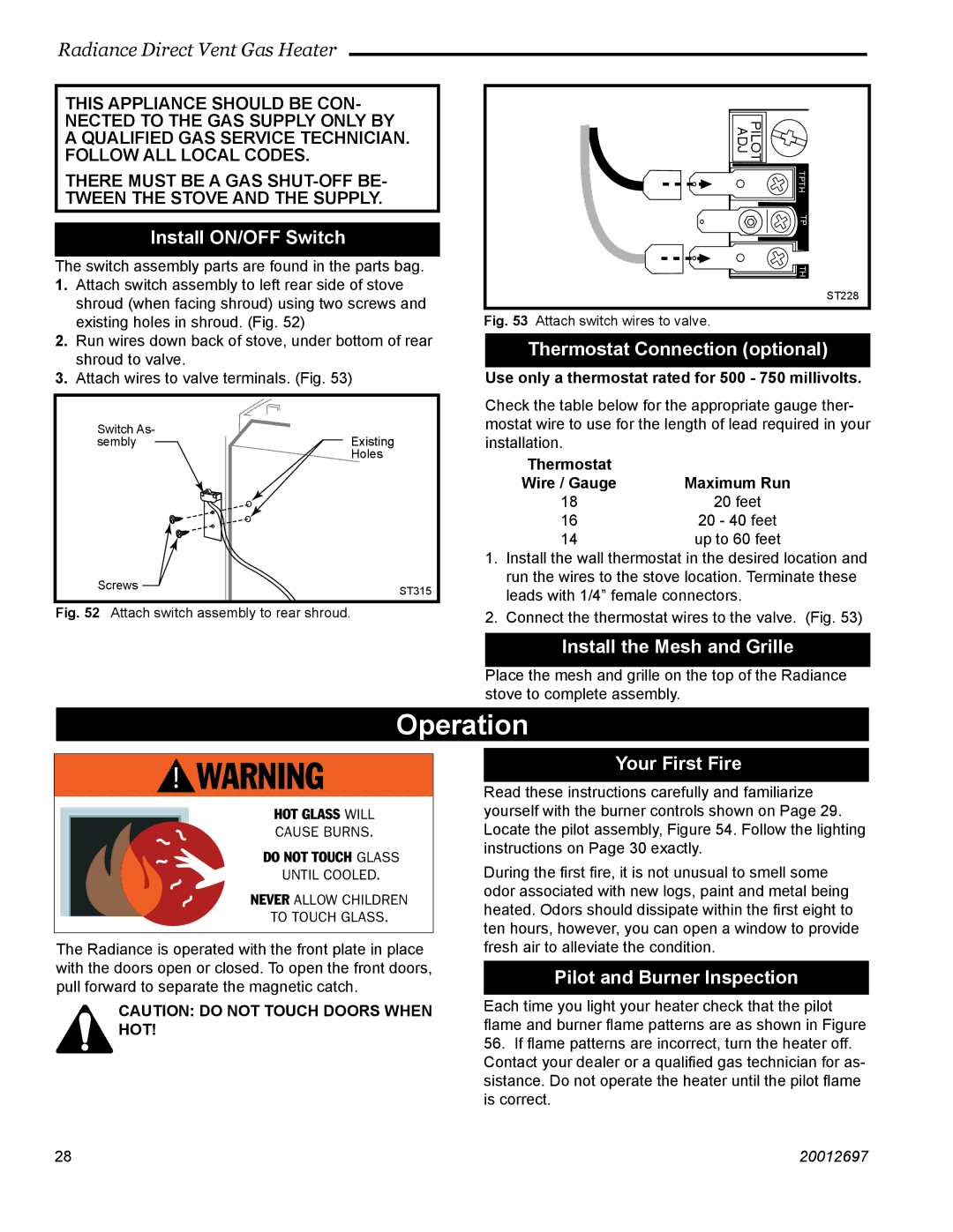
2.Run wires down back of stove, under bottom of rear shroud to valve.
3.Attach wires to valve terminals. (Fig. 53)
Switch As-
semblyExisting Holes
Screws | ST315 |
|
Fig. 52 Attach switch assembly to rear shroud.
TPTH TP TH
PILOT
ADJ
ST228
Fig. 53 Attach switch wires to valve.
Thermostat Connection (optional)
Use only a thermostat rated for 500 - 750 millivolts.
Check the table below for the appropriate gauge ther- mostat wire to use for the length of lead required in your installation.
Thermostat |
|
Wire / Gauge | Maximum Run |
18 | 20 feet |
16 | 20 - 40 feet |
14 | up to 60 feet |
1.Install the wall thermostat in the desired location and run the wires to the stove location. Terminate these leads with 1/4” female connectors.
2.Connect the thermostat wires to the valve. (Fig. 53)
Install the Mesh and Grille
Place the mesh and grille on the top of the Radiance stove to complete assembly.
Operation
��������
��������������
������������
������������������
�������������
��������������������
���������������
The Radiance is operated with the front plate in place with the doors open or closed. To open the front doors, pull forward to separate the magnetic catch.
Your First Fire
Read these instructions carefully and familiarize yourself with the burner controls shown on Page 29. Locate the pilot assembly, Figure 54. Follow the lighting instructions on Page 30 exactly.
During the first fire, it is not unusual to smell some odor associated with new logs, paint and metal being heated. Odors should dissipate within the first eight to ten hours, however, you can open a window to provide fresh air to alleviate the condition.
Pilot and Burner Inspection
CAUTION: DO NOT TOUCH DOORS WHEN HOT!
Each time you light your heater check that the pilot flame and burner flame patterns are as shown in Figure
56.If flame patterns are incorrect, turn the heater off. Contact your dealer or a qualified gas technician for as- sistance. Do not operate the heater until the pilot flame is correct.
2828 | 20012697 |