Installation
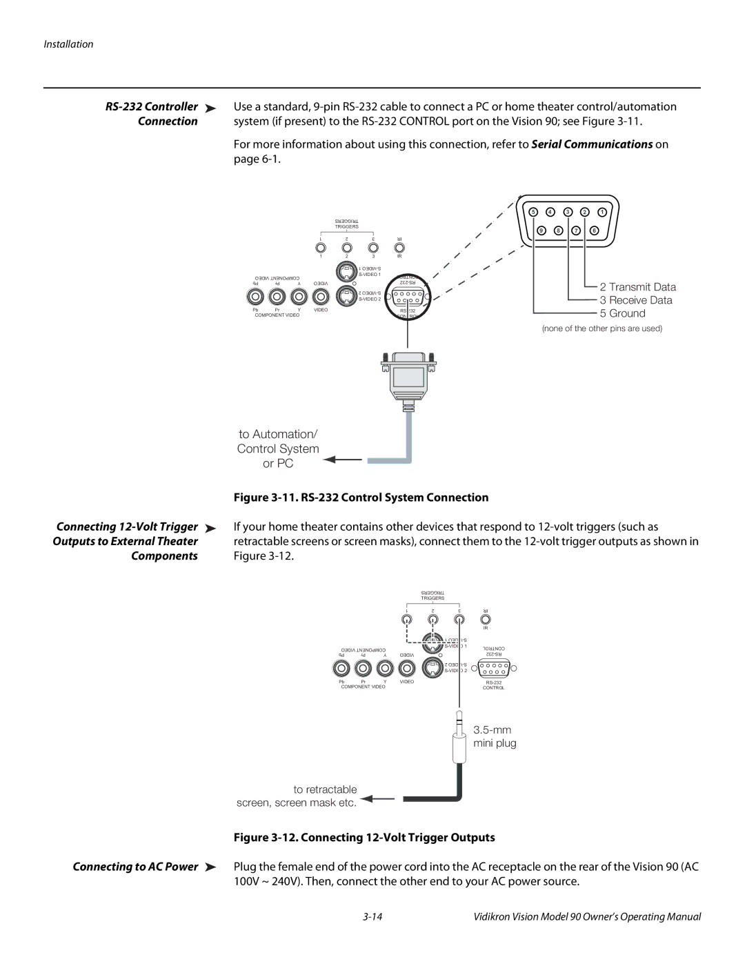
➤ | Use a standard, | |
Connection |
| system (if present) to the |
|
| For more information about using this connection, refer to Serial Communications on |
|
| page |
|
|
|
| TRIGGERS |
|
|
|
|
|
| TRIGGERS |
|
|
|
|
| 1 | 2 | 3 | IR |
|
|
| 1 | 2 | 3 | IR |
|
|
|
|
| 1 |
|
VIDEO COMPONENT |
|
| CONTROL | |||
|
|
| ||||
Pb | Pr | Y | VIDEO |
|
| |
|
|
|
|
| 2 |
|
|
|
|
|
|
| |
Pb | Pr | Y | VIDEO |
|
| |
COMPONENT VIDEO |
|
|
| CONTROL | ||
5 4 3 2 1
9 8 7 6
2 Transmit Data
3 Receive Data
5 Ground
(none of the other pins are used)
|
|
|
|
|
|
|
|
|
|
|
|
|
|
|
|
|
|
|
|
|
|
|
|
|
|
|
| to Automation/ |
|
|
|
| |||
| Control System |
|
|
|
| |||
| or PC |
|
|
|
|
|
|
|
|
|
|
|
|
|
|
| |
| Figure | |||||||
Connecting | If your home theater contains other devices that respond to | |||||||
Outputs to External Theater | retractable screens or screen masks), connect them to the | |||||||
Components | Figure | |||||||
|
|
|
|
|
| TRIGGERS | ||
|
|
|
|
|
| TRIGGERS | ||
|
|
|
|
|
|
|
|
|
|
|
| 1 |
|
|
| 1 |
VIDEO COMPONENT | VIDEO | ||
Pb | Pr | Y | |
Pb Pr Y VIDEO COMPONENT VIDEO
2 | 3 | IR |
2 | 3 | IR |
| 1 |
|
| CONTROL | |
|
| |
|
| |
| 2 |
|
|
| |
|
| |
|
| CONTROL |
to retractable screen, screen mask etc. ![]()
Figure 3-12. Connecting 12-Volt Trigger Outputs
Connecting to AC Power ➤ Plug the female end of the power cord into the AC receptacle on the rear of the Vision 90 (AC 100V ~ 240V). Then, connect the other end to your AC power source.
Vidikron Vision Model 90 Owner’s Operating Manual |