Setup
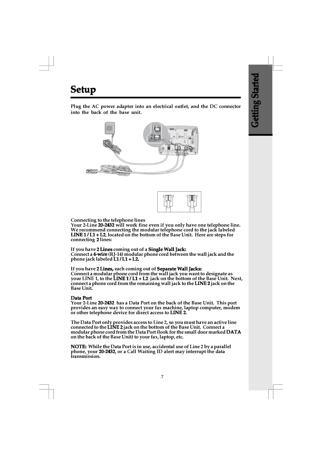
Plug the AC power adapter into an electrical outlet, and the DC connector into the back of the base unit.
To AC outlet | ! |
|
DC 7V |
| |
| 7V DC | ! |
| LINE 1/ L1 + L2 | LINE 2 |
To telephone | AC adapter |
|
socket outlet |
| |
|
| |
|
| To telephone |
|
| jack |
| Examples of | |
| ||
| One line | 2 line |
| cord | cord |
Connecting to the telephone lines
Your
If you have 2 Lines coming out of a Single Wall Jack:
Connect a
If you have 2 Lines, each coming out of Separate Wall Jacks:
Connect a modular phone cord from the wall jack you want to designate as your LINE 1, to the LINE 1 / L1 + L2 jack on the bottom of the Base Unit. Next, connect a phone cord from the remaining wall jack to the LINE 2 jack on the Base Unit.
Data Port
Your
The Data Port only provides access to Line 2, so you must have an active line connected to the LINE 2 jack on the bottom of the Base Unit. Connect a modular phone cord from the Data Port (look for the small door marked DATA on the back of the Base Unit) to your fax, laptop, etc.
NOTE: While the Data Port is in use, accidental use of Line 2 by a parallel phone, your
Getting Started
7