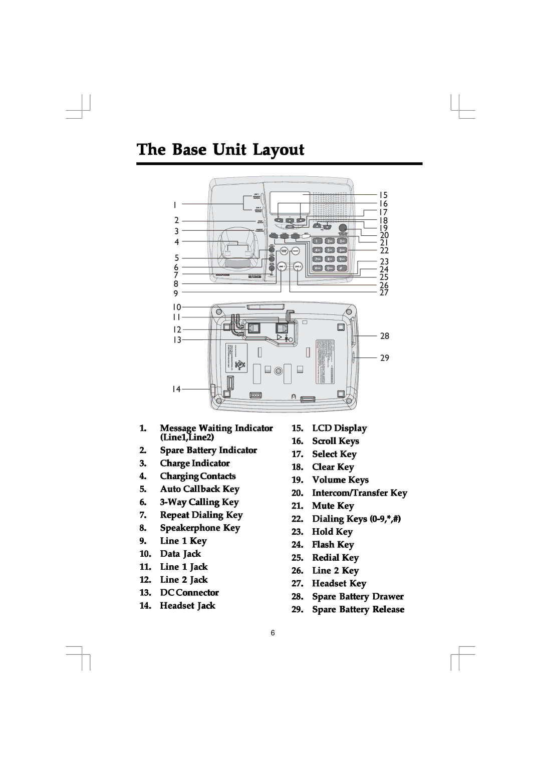
The Base Unit Layout
1
2
3
4 ![]()
5
6
7
8
9
10
11
12
13
14


 LINE 2
LINE 1/
L1 + L2
 7V DC
7V DC
 !
!
VTECH TELECOMMUNICATIONS | MODEL : 20 - 2432 |
.LTD |
|
15
16
17
18
19 ![]()
![]() 20
20 ![]()
![]() 21
21 ![]() 22
22
23
24
25
26
27
28
29
1. | Message Waiting Indicator | 15. | LCD Display | |
| (Line1,Line2) | 16. | Scroll Keys | |
2. | Spare Battery Indicator | |||
17. | Select Key | |||
3. | Charge Indicator | |||
18. | Clear Key | |||
4. | ChargingContacts | |||
19. | Volume Keys | |||
5. | Auto Callback Key | |||
20. | Intercom/Transfer Key | |||
6. | ||||
21. | Mute Key | |||
7. | Repeat Dialing Key | |||
22. | Dialing Keys | |||
8. | Speakerphone Key | |||
23. | Hold Key | |||
9. | Line 1 Key | |||
24. | Flash Key | |||
10. | Data Jack | |||
25. | Redial Key | |||
11. | Line 1 Jack | |||
26. | Line 2 Key | |||
12. | Line 2 Jack | |||
27. | Headset Key | |||
13. | DC Connector | |||
28. | Spare Battery Drawer | |||
14. | Headset Jack | |||
29. | Spare Battery Release | |||
|
|
6
