
WDTC-20 specifications
The Wayne-Dalton WDTC-20 is an innovative and versatile garage door opener that stands out in terms of performance, security, and user-friendliness. Designed by Wayne-Dalton, a leader in the garage door industry, the WDTC-20 incorporates modern technologies to provide homeowners with a complete solution for their garage access needs.One of the main features of the WDTC-20 is its powerful motor which delivers reliable lifting force suitable for standard and heavier doors. The unit is engineered to ensure smooth and quiet operation, making it ideal for residential use where noise reduction is a priority. The opener is compatible with various door types, allowing for easy integration with sectional or one-piece garage doors.
The WDTC-20 incorporates advanced security technology with its rolling code feature. This system generates a new code every time the remote is used, significantly reducing the risk of unauthorized access. Additionally, the opener includes a secure manual release system, providing peace of mind in case of power outages.
A hallmark of the WDTC-20 is its user-friendly interface. The opener features a bright LED lighting system that illuminates the garage space, enhancing visibility during entry and exit. The unit also boasts a wireless keypad option that allows users to open the garage door without needing to carry a remote. This is particularly convenient for households with multiple users.
For tech-savvy homeowners, the WDTC-20 offers smartphone compatibility through its smart hub. By connecting to a home Wi-Fi network, users can control and monitor the garage door remotely via a mobile app. This feature allows notifications for door status, facilitating enhanced security and operability.
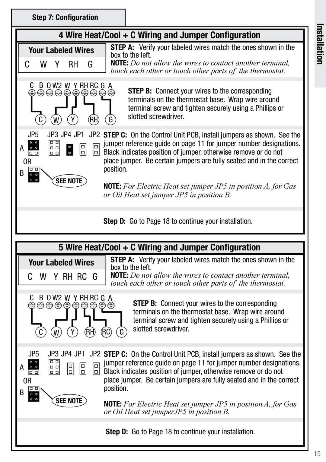
In terms of installation, the WDTC-20 is designed for easy and straightforward setup, enabling users to quickly benefit from its extensive features. Additionally, Wayne-Dalton offers robust customer support and a warranty program for peace of mind.
Overall, the Wayne-Dalton WDTC-20 combines strength, security, and technological innovation, making it a compelling choice for anyone in need of a modern garage door opener. Its blend of convenience and safety features ensures that it caters well to the dynamic needs of contemporary living.