MAINTENANCE
SIDE BURNER MAINTENANCE
m WARNING: All gas controls and supply valves should be in the OFF position.
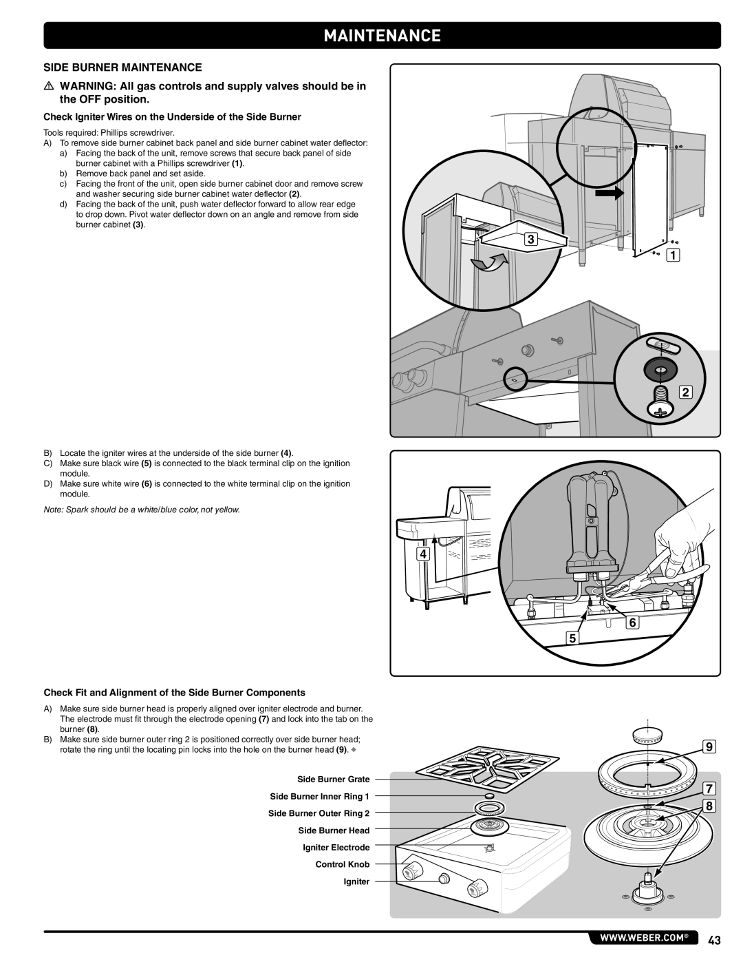
Check Igniter Wires on the Underside of the Side Burner
Tools required: Phillips screwdriver..
A) To remove side burner cabinet back panel and side burner cabinet water deflector:
a)Facing the back of the unit, remove screws that secure back panel of side burner cabinet with a Phillips screwdriver (1)..
b)Remove back panel and set aside..
c)Facing the front of the unit, open side burner cabinet door and remove screw
and washer securing side burner cabinet water deflector (2)..
d)Facing the back of the unit, push water deflector forward to allow rear edge
to drop down.. Pivot water deflector down on an angle and remove from side burner cabinet (3)..
3
1
2
B)Locate the igniter wires at the underside of the side burner (4)..
C)Make sure black wire (5) is connected to the black terminal clip on the ignition
module..
D)Make sure white wire (6) is connected to the white terminal clip on the ignition module..
Note: Spark should be a white/blue color, not yellow.
4
6
5
Check Fit and Alignment of the Side Burner Components
A)Make sure side burner head is properly aligned over igniter electrode and burner.. The electrode must fit through the electrode opening (7) and lock into the tab on the burner (8)..
B)Make sure side burner outer ring 2 is positioned correctly over side burner head;
rotate the ring until the locating pin locks into the hole on the burner head (9).. ◆
Side Burner Grate
Side Burner Inner Ring 1
Side Burner Outer Ring 2
Side Burner Head
Igniter Electrode
Control Knob
Igniter
9
7 ![]()
![]() 8
8
www.weber.com® 43