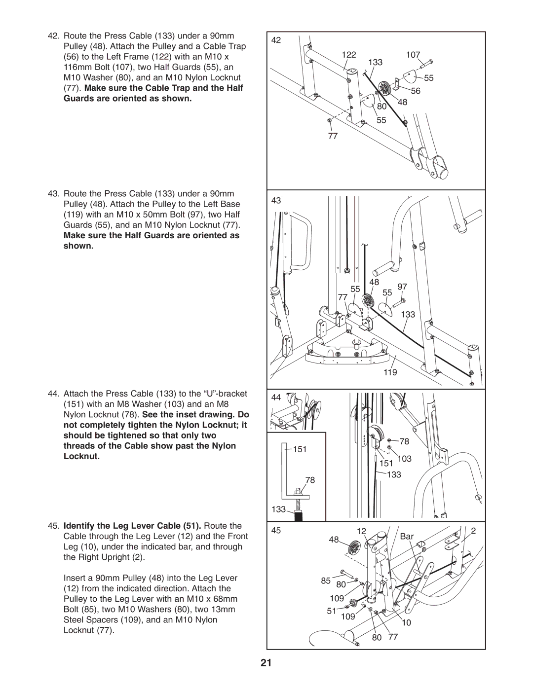
42. Route the Press Cable (133) under a 90mm | 42 |
|
|
|
|
| |
| Pulley (48). Attach the Pulley and a Cable Trap |
|
|
|
|
| |
|
|
| 122 |
| 107 |
| |
| (56) to the Left Frame (122) with an M10 x |
|
|
|
| ||
| 116mm Bolt (107), two Half Guards (55), an |
|
| 133 |
|
|
|
|
|
|
|
|
|
| |
| M10 Washer (80), and an M10 Nylon Locknut |
|
|
|
|
| 55 |
| (77). Make sure the Cable Trap and the Half |
|
|
|
| 56 |
|
| Guards are oriented as shown. |
|
|
|
|
| |
|
|
| 80 | 48 |
| ||
|
|
|
|
| |||
|
|
|
|
|
| ||
|
|
|
| 55 |
|
| |
|
|
| 77 |
|
|
| |
43. Route the Press Cable (133) under a 90mm | 43 |
|
|
|
|
| |
| Pulley (48). Attach the Pulley to the Left Base |
|
|
|
|
| |
|
|
|
|
|
|
| |
| (119) with an M10 x 50mm Bolt (97), two Half |
|
|
|
|
|
|
| Guards (55), and an M10 Nylon Locknut (77). |
|
|
|
|
|
|
| Make sure the Half Guards are oriented as |
|
|
|
|
|
|
| shown. |
|
|
|
|
|
|
|
|
|
| 48 |
| 97 |
|
|
|
|
| 55 | 55 |
| |
|
|
|
| 77 |
|
| |
|
|
|
|
|
|
| |
|
|
|
|
|
| 133 |
|
|
|
|
|
| 119 |
|
|
44. | Attach the Press Cable (133) to the | 44 |
|
|
|
|
|
| (151) with an M8 Washer (103) and an M8 |
|
|
|
|
| |
|
|
|
|
|
|
| |
| Nylon Locknut (78). See the inset drawing. Do |
|
|
|
|
|
|
| not completely tighten the Nylon Locknut; it |
|
|
|
|
|
|
| should be tightened so that only two |
|
|
|
| 78 |
|
| threads of the Cable show past the Nylon |
| 151 |
|
|
| |
|
|
|
|
|
| ||
| Locknut. |
|
|
| 103 |
| |
|
|
| 151 |
| |||
|
|
|
|
| |||
|
|
| 78 |
| 133 |
| |
|
|
|
|
|
|
| |
|
| 133 |
|
|
|
|
|
45. Identify the Leg Lever Cable (51). Route the | 45 |
| 12 |
|
| 2 | |
| Cable through the Leg Lever (12) and the Front |
|
| Bar | |||
|
| 48 |
|
| |||
| Leg (10), under the indicated bar, and through |
|
|
|
| ||
|
|
|
|
|
|
| |
| the Right Upright (2). |
|
|
|
|
|
|
| Insert a 90mm Pulley (48) into the Leg Lever |
| 85 | 80 |
|
|
|
| (12) from the indicated direction. Attach the |
|
|
|
| ||
|
|
|
|
|
|
| |
| Pulley to the Leg Lever with an M10 x 68mm |
| 109 |
|
|
| |
| Bolt (85), two M10 Washers (80), two 13mm |
| 51 109 |
|
|
| |
| Steel Spacers (109), and an M10 Nylon |
|
| 10 |
| ||
|
|
|
|
|
| ||
| Locknut (77). |
|
|
|
|
| |
|
|
| 80 | 77 |
| ||
|
|
|
|
| |||
|
| 21 |
|
|
|
|
|
