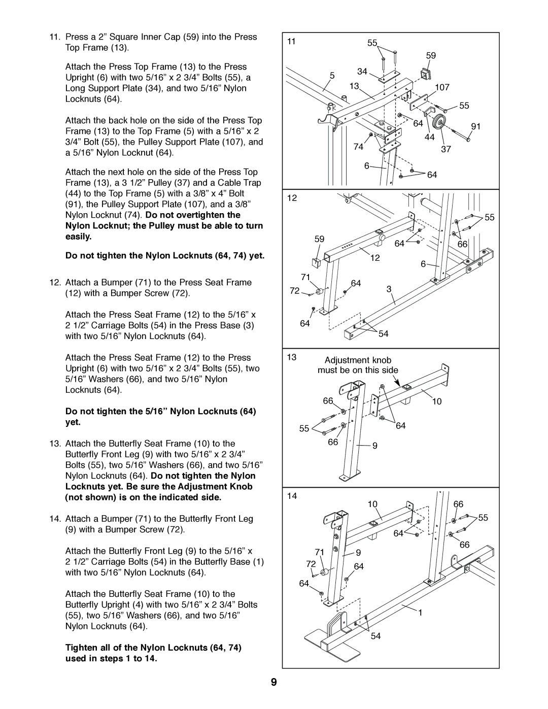
11.Press a 2” Square Inner Cap (59) into the Press Top Frame (13).
Attach the Press Top Frame (13) to the Press Upright (6) with two 5/16” x 2 3/4” Bolts (55), a Long Support Plate (34), and two 5/16” Nylon Locknuts (64).
Attach the back hole on the side of the Press Top Frame (13) to the Top Frame (5) with a 5/16” x 2 3/4” Bolt (55), the Pulley Support Plate (107), and a 5/16” Nylon Locknut (64).
Attach the next hole on the side of the Press Top Frame (13), a 3 1/2” Pulley (37) and a Cable Trap (44) to the Top Frame (5) with a 3/8” x 4” Bolt (91), the Pulley Support Plate (107), and a 3/8” Nylon Locknut (74). Do not overtighten the
Nylon Locknut; the Pulley must be able to turn easily.
Do not tighten the Nylon Locknuts (64, 74) yet.
12.Attach a Bumper (71) to the Press Seat Frame (12) with a Bumper Screw (72).
Attach the Press Seat Frame (12) to the 5/16” x 2 1/2” Carriage Bolts (54) in the Press Base (3) with two 5/16” Nylon Locknuts (64).
Attach the Press Seat Frame (12) to the Press Upright (6) with two 5/16” x 2 3/4” Bolts (55), two 5/16” Washers (66), and two 5/16” Nylon Locknuts (64).
Do not tighten the 5/16” Nylon Locknuts (64) yet.
13.Attach the Butterfly Seat Frame (10) to the Butterfly Front Leg (9) with two 5/16” x 2 3/4” Bolts (55), two 5/16” Washers (66), and two 5/16” Nylon Locknuts (64). Do not tighten the Nylon
Locknuts yet. Be sure the Adjustment Knob (not shown) is on the indicated side.
14.Attach a Bumper (71) to the Butterfly Front Leg
(9) with a Bumper Screw (72).
Attach the Butterfly Front Leg (9) to the 5/16” x
2 1/2” Carriage Bolts (54) in the Butterfly Base (1) with two 5/16” Nylon Locknuts (64).
Attach the Butterfly Seat Frame (10) to the Butterfly Upright (4) with two 5/16” x 2 3/4” Bolts (55), two 5/16” Washers (66), and two 5/16” Nylon Locknuts (64).
Tighten all of the Nylon Locknuts (64, 74) used in steps 1 to 14.
11 |
|
| 55 |
|
|
|
|
|
| 59 |
|
| 5 | 34 |
|
| |
|
|
|
|
| |
|
| 13 |
| 107 |
|
|
|
|
|
| 55 |
|
|
|
| 64 | 91 |
|
|
|
|
| |
|
| 74 |
| 44 |
|
|
|
| 37 |
| |
|
|
| 6 | 64 |
|
|
|
|
|
| |
12 |
|
|
|
|
|
|
|
|
|
| 55 |
| 59 |
| 64 |
| 66 |
|
|
|
| ||
|
|
| 12 | 6 |
|
|
|
|
|
| |
| 71 | 64 |
|
|
|
72 | 3 |
|
| ||
|
|
| |||
| 64 |
|
|
|
|
|
|
| 54 |
|
|
13 | Adjustment knob |
|
| ||
|
|
| |||
| must be on this side |
|
| ||
| 66 |
|
| 10 |
|
| 55 |
| 64 |
|
|
|
|
|
|
| |
| 66 |
| 9 |
|
|
|
|
|
|
| |
14 |
|
| 10 |
| 66 |
|
|
|
| ||
|
|
|
|
| 55 |
|
|
| 64 |
|
|
| 71 | 9 |
|
| 66 |
|
|
|
| ||
| 72 | 64 |
|
|
|
| 64 |
|
|
|
|
|
|
|
| 1 |
|
|
|
| 54 |
|
|
9
