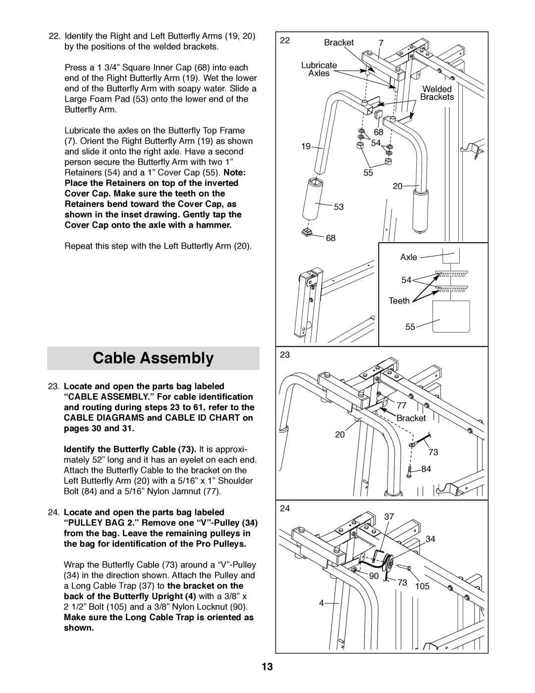
22. Identify the Right and Left Butterfly Arms (19, 20) | 22 | Bracket | 7 |
|
by the positions of the welded brackets. |
| |||
|
|
|
| |
Press a 1 3/4” Square Inner Cap (68) into each |
| Lubricate |
|
|
end of the Right Butterfly Arm (19). Wet the lower |
| Axles |
|
|
|
|
|
| |
end of the Butterfly Arm with soapy water. Slide a |
|
|
| Welded |
Large Foam Pad (53) onto the lower end of the |
|
|
| Brackets |
Butterfly Arm. |
|
|
|
|
Lubricate the axles on the Butterfly Top Frame |
|
| 68 |
|
(7). Orient the Right Butterfly Arm (19) as shown |
| 19 | 54 |
|
and slide it onto the right axle. Have a second |
|
|
| |
|
|
|
| |
person secure the Butterfly Arm with two 1” |
|
|
|
|
Retainers (54) and a 1” Cover Cap (55). Note: |
|
| 55 |
|
Place the Retainers on top of the inverted |
|
| 20 |
|
Cover Cap. Make sure the teeth on the |
|
|
| |
|
|
|
| |
Retainers bend toward the Cover Cap, as |
| 53 |
|
|
shown in the inset drawing. Gently tap the |
|
|
| |
|
|
|
| |
Cover Cap onto the axle with a hammer. |
|
|
|
|
Repeat this step with the Left Butterfly Arm (20). |
| 68 |
|
|
|
|
|
| |
|
|
| Axle | |
|
|
| 54 |
|
|
|
| Teeth |
|
|
|
| 55 | |
Cable Assembly | 23 |
|
|
|
|
|
|
| |
23. Locate and open the parts bag labeled |
|
|
|
|
“CABLE ASSEMBLY.” For cable identification |
|
| 77 |
|
and routing during steps 23 to 61, refer to the |
|
|
| |
CABLE DIAGRAMS and CABLE ID CHART on |
|
| Bracket | |
pages 30 and 31. |
| 20 |
|
|
|
|
|
| |
Identify the Butterfly Cable (73). It is approxi- |
|
|
| 73 |
mately 52” long and it has an eyelet on each end. |
|
|
| |
|
|
| 84 | |
Attach the Butterfly Cable to the bracket on the |
|
|
| |
Left Butterfly Arm (20) with a 5/16” x 1” Shoulder |
|
|
|
|
Bolt (84) and a 5/16” Nylon Jamnut (77). |
|
|
|
|
24. Locate and open the parts bag labeled | 24 |
| 37 |
|
|
|
| ||
“PULLEY BAG 2.” Remove one |
|
|
| |
|
|
|
| |
from the bag. Leave the remaining pulleys in |
|
|
| 34 |
the bag for identification of the Pro Pulleys. |
|
|
| |
|
|
|
| |
Wrap the Butterfly Cable (73) around a |
|
|
|
|
(34) in the direction shown. Attach the Pulley and |
|
| 90 |
|
a Long Cable Trap (37) to the bracket on the |
|
| 73 | 105 |
back of the Butterfly Upright (4) with a 3/8” x |
| 4 |
|
|
2 1/2” Bolt (105) and a 3/8” Nylon Locknut (90). |
|
|
| |
|
|
|
| |
Make sure the Long Cable Trap is oriented as |
|
|
|
|
shown. |
|
|
|
|
13
