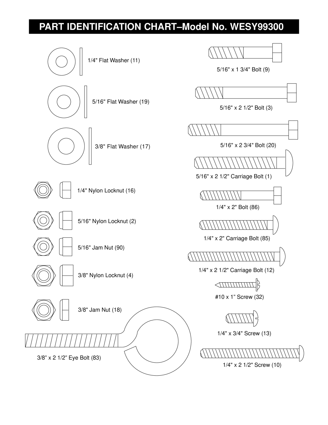
Visit our website at
QUESTIONS?
USER’S MANUAL
Model No. WESY99300 Serial No
ICON OF/DU CANADA, 900 de l’Industrie, St-Jérôme, QC J7Y 4B8
TABLE OF CONTENTS
LIMITED WARRANTY
WEIDER is a registered trademark of ICON Health & Fitness, Inc
1. Read all instructions in this manual and in
IMPORTANT PRECAUTIONS
away from the weight system at all times
5. Regularly inspect and tighten all parts
BEFORE YOU BEGIN
using the weight system
ASSEMBLY
the head of each Bolt
Frame Assembly
Locate and open the parts bag labelled “FRAME ASSEMBLY.”
Locknuts 2 onto the Bolts
1717
Attach the Weight Guides 58 to the Butterfly Base
Pin Grooves
4Lubricate
the Nylon Locknuts yet
Secure the Weight Guides 58 to the Butterfly Top
2. Note Before attaching the Top Frames to the
61 with the indicated 5/16” x 2 1/2” Carriage Bolts
9. Locate and open the parts bag labelled “ARM
Arm Assembly
ASSEMBLY.”
Note The Plastic
Lever must pivot easily
Cable Assembly
Nut 90. Do not overtighten the Jam Nut. The Leg
Identify the Short Cable 71. It has a closed loop on
Welded
Nylon Locknut
Butterfly Upright 62 in the same manner
Bracket
end and a loop on the other
and a 3/8” Nylon Locknut
Locknut
Butterfly Base
Bracket
Nylon Locknut 4. Make sure that the Cable Trap is oriented as shown
Base 61 with a 3/8” x 2” Bolt 35 and a 3/8” Nylon Locknut
53 with a 3/8” x 3 1/4” Bolt 28, a 3/8” Flat Washer
27. Wrap the Long Cable 73 around the 3 1/2” Pulley
er Pulley will be attached to the Bolt
17, and a 3/8” Nylon Locknut 4. Make sure that
Washer 17, and a 3/8” Nylon Locknut
small tube has three adjustment holes. Mount the
Frame 52 with a 3/8” x 3 1/4” Bolt 28, a 3/8” Flat
is oriented as shown
x 2” Bolt 86 and a 1/4” Flat Washer
Seat Assembly
33. Locate and open the parts bag labelled “SEAT ASSEMBLY.”
34. Press four 3/4” Round Inner Caps 40 into the ends
Seat 51 with two 1/4” x 3/4” Screws
39. Apply the WEIDER PRO 9930 decal in the location shown
ADJUSTMENT, beginning on page 21 of this manual
AND MAINTENANCE on page
WEIDER
Cable ID Chart
CABLE DIAGRAMS
bind the Cables. Incorrect cable routing can damage the weight system
71 1.9m 6 ft. 3 in 72 3.5m 11 ft. 6 in 73 7.6m 24 ft. 11 in
Long Cable
CHANGING THE WEIGHT SETTING
ADJUSTMENT
Important When using
find the approximate amount of resistance at each weight station
TIGHTENING THE CABLES
TROUBLE-SHOOTING AND MAINTENANCE
Note If additional adjustment is need
ed, move the other Pulley
Note The actual resistance at each station may
WEIGHT RESISTANCE CHART
Weight
High
PRO 9930 weight system
ORDERING REPLACEMENT PARTS
PRODUCT WARRANTY REGISTRATION
1. The MODEL NUMBER of the product WESY99300
R0501A
REMOVE THIS PART IDENTIFICATION CHART FROM THE MANUAL
until you begin each stage to open the parts bag for that stage
5/16 Nylon Locknut 5/16 Jam Nut 3/8 Nylon Locknut 3/8 Jam Nut
PART IDENTIFICATION CHART-Model No. WESY99300
1/4 Flat Washer 5/16 Flat Washer 3/8 Flat Washer 1/4 Nylon Locknut
3/8” x 2 1/2” Eye Bolt
3/8 x 1 3/4 Bolt 3 1/2 Pulley Not shown to scale 3/8 x 2 Bolt
1/4 x 1 1/2 Screw
3/8 x 1 Bolt
4 1/2 Pulley Not shown to scale 3/8 x 2 1/4 Bolt Cable Clip
1 1/2 Square Inner Cap 2 Square Inner Cap
3/4 Round Inner Cap 1 x 7/8 Plastic Bushing 1 Round Cap
1 Round Inner Cap 1 Inner Cap 1 3/4 Square Inner Cap
REMOVE THIS PART LIST/EXPLODED DRAWING FROM THE MANUAL
Description
PART LIST-Model No. WESY99300
R0501A
Key No. Qty
R0501A
Model No. WESY99300
EXPLODED DRAWING
18 71