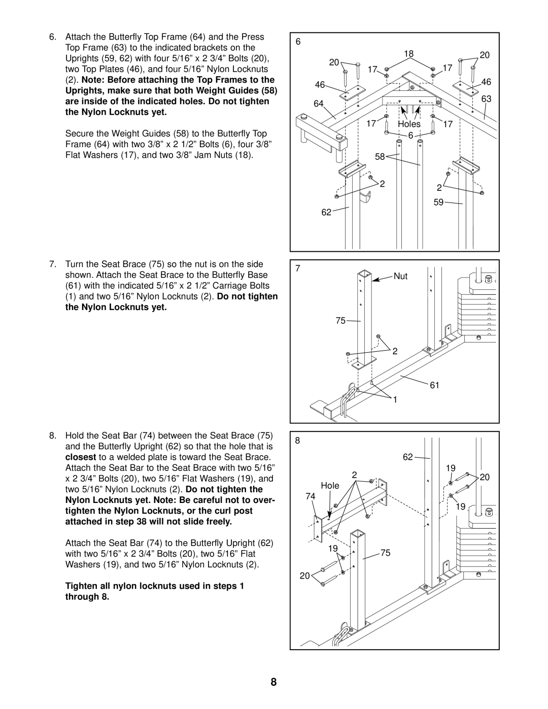
6.Attach the Butterfly Top Frame (64) and the Press Top Frame (63) to the indicated brackets on the
Uprights (59, 62) with four 5/16” x 2 3/4” Bolts (20), two Top Plates (46), and four 5/16” Nylon Locknuts
(2). Note: Before attaching the Top Frames to the
Uprights, make sure that both Weight Guides (58) are inside of the indicated holes. Do not tighten
the Nylon Locknuts yet.
Secure the Weight Guides (58) to the Butterfly Top
Frame (64) with two 3/8” x 2 1/2” Bolts (6), four 3/8” Flat Washers (17), and two 3/8” Jam Nuts (18).
7.Turn the Seat Brace (75) so the nut is on the side shown. Attach the Seat Brace to the Butterfly Base
(61)with the indicated 5/16” x 2 1/2” Carriage Bolts
(1) and two 5/16” Nylon Locknuts (2). | Do not tighten |
the Nylon Locknuts yet. |
|
8. Hold the Seat Bar (74) between the Seat Brace (75) and the Butterfly Upright (62) so that the hole that is
closest | to a welded plate is toward the Seat Brace. | |
Attach the Seat Bar to the Seat Brace with two 5/16” | ||
x 2 3/4” Bolts (20), two 5/16” Flat Washers (19), and | ||
two 5/16” Nylon Locknuts (2). | Do not tighten the | |
Nylon Locknuts yet. Note: Be careful not to over- tighten the Nylon Locknuts, or the curl post attached in step 38 will not slide freely.
Attach the Seat Bar (74) to the Butterfly Upright (62) with two 5/16” x 2 3/4” Bolts (20), two 5/16” Flat Washers (19), and two 5/16” Nylon Locknuts (2).
Tighten all nylon locknuts used in steps 1 through 8.
6 |
|
|
20 | 18 | 20 |
| 17 | |
17 |
| |
46 |
| 46 |
|
| |
64 |
| 63 |
|
| |
17 | Holes | 17 |
| 6 |
|
| 58 |
|
| 2 | 2 |
|
| |
62 |
| 59 |
|
| |
7 | Nut |
|
|
| |
75 |
|
|
| 2 |
|
|
| 61 |
| 1 |
|
8 |
|
|
| 62 |
|
2 |
| 19 |
| 20 | |
Hole |
|
|
74 |
|
|
|
| 19 |
19 | 75 |
|
|
| |
20 |
|
|
8