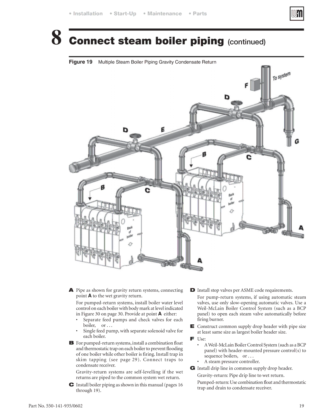
APipe as shown for gravity return systems, connecting point A to the wet gravity return.
For pumped-return systems, install boiler water level control on each boiler with body mark at level indicated in Figure 30 on page 30. Provide at point A either:
•Separate feed pumps and check valves for each
boiler, or . . .
•Single feed pump, with separate solenoid valve for each boiler.
BFor pumped-return systems, install a combination float and thermostatic trap on each boiler to prevent flooding of one boiler while other boiler is firing. Install trap in skim tapping (see page 29). Connect traps to condensate receiver.
Gravity-return systems are self-levelling if the wet returns are piped to the common system wet return.
CInstall boiler piping as shown in this manual (pages 16 through 19).
DInstall stop valves per ASME code requirements.
For pump-return systems, if using automatic steam valves, use only slow-opening automatic valves. Use a Weil-McLain Boiler Control System (such as a BCP panel) to open each steam valve automatically before firing burner.
EConstruct common supply drop header with pipe size at least same size as largest boiler header size.
FUse:
• A Weil-McLain Boiler Control System (such as a BCP
panel) with header-mounted pressure control(s) to sequence boilers, or . . .
•A steam pressure controller.
GInstall drip line in common supply drop header. Gravity-return: Pipe drip line to wet return.
Pumped-return: Use combination float and thermostatic trap and drain to condensate receiver.