![]() At this point, if your Satellite System does not need a software update, or has already been updated, you may plug the data cable inside of dome into the modular con- nection on the electronics board. Verify that all connections have been made and all cables have been tied to base using cable ties. Replace dome using 8 screws. Be sure dome screws are securely fastened. See Figure 3.3.
At this point, if your Satellite System does not need a software update, or has already been updated, you may plug the data cable inside of dome into the modular con- nection on the electronics board. Verify that all connections have been made and all cables have been tied to base using cable ties. Replace dome using 8 screws. Be sure dome screws are securely fastened. See Figure 3.3.
Figure 3.3
Note: Movin’ View board shown. RoadTrip board will be slightly different
After power/data cable and coax cable(s) have been routed to Satellite Interface, seal under- neath cable entry plate with approved sealant and screw down plate using 12 screws with drill and 5/16” nut driver. Seal over screw heads and around entry plate. Clamp excess cable with supplied cable clamps and screws. Seal around screw holes.
3.3 Plug Power Cable into Satellite Interface
If the original power cable was removed from the satellite antenna in the previous step, disconnect the power wire from the power switch inside the RV. Discard switch, wall plate, and original power cable.
Connect power/data cable power wires to green connector provided in hardware bag. Screw top screws down to secure cables. See Figure 3.4.
![]() Do not cut the power/data cable. You should coil excess cable in- side or behind the cabinet.
Do not cut the power/data cable. You should coil excess cable in- side or behind the cabinet.
Figure 3.4 | Red Wire |
|
Black Wire
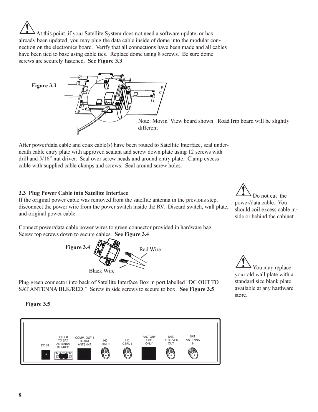
Plug green connector into back of Satellite Interface Box in port labelled “DC OUT TO SAT ANTENNA BLK/RED.” Screw in side screws to secure to box. See Figure 3.5.
Figure 3.5
![]() You may replace your old wall plate with a standard size blank plate available at any hardware store.
You may replace your old wall plate with a standard size blank plate available at any hardware store.
|
| DC OUT | COMM. OUT 1 |
|
| FACTORY | SAT. | SAT. | ||
|
| TO SAT |
| TO SAT. | HD | HD | USE | RECEIVER | ANTENNA | |
DC IN |
| ANTENNA |
| ANTENNA | CTRL 2 | CTRL 1 | ONLY | OUT | IN | |
|
| BLK/RED |
|
|
|
|
|
|
|
|
|
|
|
|
|
|
|
|
|
|
|
|
|
|
|
|
|
|
|
|
|
|
|
|
|
|
|
|
|
|
|
|
|
