46945 HOSE KIT
General Description |
|
| |
|
| ||
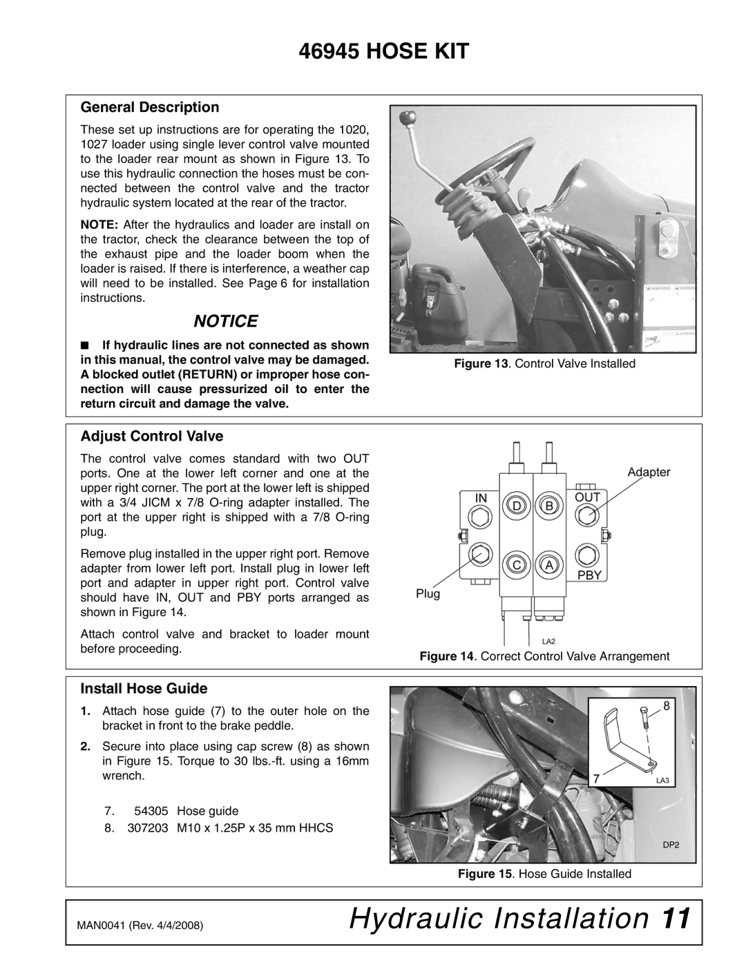
These set up instructions are for operating the 1020, |
|
| |
1027 loader using single lever control valve mounted |
|
| |
to the loader rear mount as shown in Figure 13. To |
|
| |
use this hydraulic connection the hoses must be con- |
|
| |
nected between the control valve and the tractor |
|
| |
hydraulic system located at the rear of the tractor. |
|
| |
NOTE: After the hydraulics and loader are install on |
|
| |
the tractor, check the clearance between the top of |
|
| |
the exhaust pipe and the loader boom when the |
|
| |
loader is raised. If there is interference, a weather cap |
|
| |
will need to be installed. See Page 6 for installation |
|
| |
instructions. |
|
| |
NOTICE |
|
| |
■ If hydraulic lines are not connected as shown |
|
| |
in this manual, the control valve may be damaged. | Figure 13. Control Valve Installed | ||
A blocked outlet (RETURN) or improper hose con- | |||
|
| ||
nection will cause pressurized oil to enter the |
|
| |
return circuit and damage the valve. |
|
| |
|
|
| |
|
|
| |
Adjust Control Valve |
|
| |
The control valve comes standard with two OUT |
|
| |
ports. One at the lower left corner and one at the |
|
| |
upper right corner. The port at the lower left is shipped |
|
| |
with a 3/4 JICM x 7/8 |
|
| |
port at the upper right is shipped with a 7/8 |
|
| |
plug. |
|
| |
Remove plug installed in the upper right port. Remove |
|
| |
adapter from lower left port. Install plug in lower left |
|
| |
port and adapter in upper right port. Control valve |
|
| |
should have IN, OUT and PBY ports arranged as |
|
| |
shown in Figure 14. |
|
| |
Attach control valve and bracket to loader mount
before proceeding.
Figure 14. Correct Control Valve Arrangement
Install Hose Guide
1.Attach hose guide (7) to the outer hole on the bracket in front to the brake peddle.
2.Secure into place using cap screw (8) as shown in Figure 15. Torque to 30
7.54305 Hose guide
8.307203 M10 x 1.25P x 35 mm HHCS
DP2
Figure 15. Hose Guide Installed
MAN0041 (Rev. 4/4/2008) | Hydraulic Installation 11 |
|
|