1. | Tongue | 28 |
| |
10 | 11 | |||
2. | Tongue lug | |||
29 |
|
3.Tongue adjustment bracket
4.Compression member
5. |
|
|
|
| 30 | |
|
|
|
|
| ||
6. | Mast plate |
|
|
|
|
|
7. | Compression bracket |
|
|
|
| 32 |
8. | Rear |
|
|
|
|
|
9. | Carrier bearing housing |
|
| 9 | 8 | |
10. | Drive shaft shield |
|
|
|
|
|
11. | Clamp bolt |
|
| 32 |
|
|
12. | 5/8 x |
|
|
|
|
|
13. | 5/8" Flat washer |
|
|
|
|
|
14. | 5/8 x 7/8 x 11/16" Bushing | 23 | 24 |
| 28 | |
15. | 5/8" Lock washer |
|
| |||
| 25 |
|
| |||
|
| 17 |
| |||
16. | 5/8" Hex nut |
|
|
| ||
17 |
| 20 | 7 | |||
|
| |||||
17. | 3/16 x 1" Cotter pin |
|
| |||
|
|
|
| 31 | ||
18. | 5/8 x |
|
| 21 | 20 | |
22 |
|
| ||||
| 27 |
| 6 |
|
| |
|
| 5 |
| 26 | ||
|
|
|
|
| ||
|
| 4 |
|
| 21 |
|
|
|
|
| 16 |
|
|
|
| 20 |
| 15 |
| 14 |
| 21 |
| 2 |
| 13 | |
|
|
|
|
| 12 | |
|
|
|
| 1 |
| |
|
| 3 |
|
|
| |
|
|
| 18 |
|
| |
|
|
|
| 17 | CD3823A |
|
|
|
|
| 19 |
|
|
19. 1/2 x |
|
| 24. 1/2" Schedule 40 x | 28. 3/8 x 1" Bolt | ||
20. 1/2" Heavy lock washer |
| pipe |
| 29. 3/8" Lock washer | ||
21. 1/2" Heavy hex nut |
|
| 25. 1/2 x 2" Clevis pin |
| 30. 1/4 x 3" Cotter pin | |
22. 1/2 x |
| 26. 1/2 x |
| 31. 3/8" Flanged lock nut | ||
23. 1/2 x |
|
| 27. Parking jack |
| 32. Tether chain | |
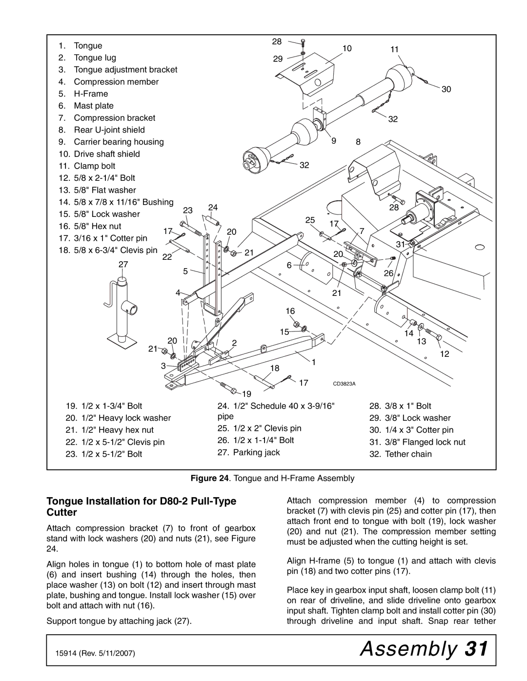
Figure 24. Tongue and H-Frame Assembly
Tongue Installation for D80-2 Pull-Type Cutter
Attach compression bracket (7) to front of gearbox stand with lock washers (20) and nuts (21), see Figure 24.
Align holes in tongue (1) to bottom hole of mast plate
(6)and insert bushing (14) through the holes, then place washer (13) on bolt (12) and insert through mast plate, bushing and tongue. Install lock washer (15) over bolt and attach with nut (16).
Support tongue by attaching jack (27).
Attach compression member (4) to compression bracket (7) with clevis pin (25) and cotter pin (17), then attach front end to tongue with bolt (19), lock washer
(20)and nut (21). The compression member setting must be adjusted when the cutting height is set.
Align
Place key in gearbox input shaft, loosen clamp bolt (11) on rear of driveline, and slide driveline onto gearbox input shaft. Tighten clamp bolt and install cotter pin (30) through driveline and input shaft. Snap rear tether
15914 (Rev. 5/11/2007) | Assembly 31 |
|
|