chain (32) around the compression link to prevent driv- eline shield rotation.
Align driveline in
Attach rear universal joint shield (8) to gear stand as shown with bolts (28) and nuts (31). Place forward driv- eline shield (10) over
Attach pipe (24) to
(20)and nut (21). Attach front tether chain (32) securely to tractor.
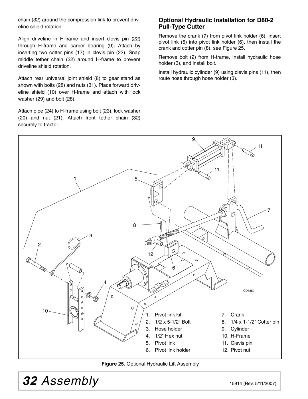
Optional Hydraulic Installation for D80-2 Pull-Type Cutter
Remove the crank (7) from pivot link holder (6), insert pivot link (5) into pivot link holder (6), then install the crank and cotter pin (8), see Figure 25.
Remove bolt (2) from
Install hydraulic cylinder (9) using clevis pins (11), then route hose through hose holder (3).
1. | Pivot link kit | 7. | Crank |
2. | 1/2 x | 8. | 1/4 x |
3. | Hose holder | 9. | Cylinder |
4. | 1/2" Hex nut | 10. | |
5. | Pivot link | 11. | Clevis pin |
6. | Pivot link holder | 12. | Pivot nut |
Figure 25. Optional Hydraulic Lift Assembly
32 Assembly | 15914 (Rev. 5/11/2007) |
|
|