1.Hitch pin
2.Mast plate
3.
4.7/8 x
5.Support brace
6.3/4" Flat washer
7.13/16 x
8. | 3/4" Slotted hex nut |
|
| 29. | 3/8 x 1" Bolt |
9. | 5/8 x |
|
| 30. | 3/8" Flange hex nut |
10. | 5/8" Hex lock nut |
|
| 31. | Rear |
11. | 3/4 x | 20. | Tailwheel | 32. | 3/16 x |
12. | Lift channel | 21. | 5/8" Elastic stop nut | 33. | 3/8 x 3/8 x 2" Key |
13. | Spacer bushing | 22. | 5/8 x 2" Bolt | 34. | Rear drive half |
14. | 3/4" Hex lock nut | 23. | 5/8 x | 35. | Clamp bolt |
15. | Top link pin | 24. | 5/8" Flat washer | 36. | 1/2" Lock washer |
16. | 5/8 x | 25. | 3/4 x 8" Clevis pin | 37. | 1/2" Hex nut |
17. | Hitch stop | 26. | Tailwheel mounting bracket | 38. | 1/4 x 3" Cotter pin |
18. | 5/8 x | 27. | Rebound pad support | 39. | 3/8" Flange lock nut |
19. | Tailwheel arm bracket | 28. | Rebound pad | 40. | Tether chain |
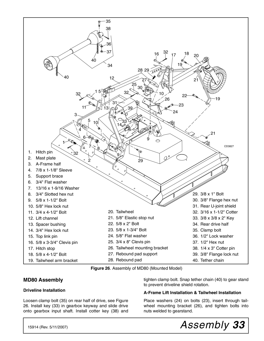
| Figure 26. Assembly of MD80 (Mounted Model) |
MD80 Assembly | tighten clamp bolt. Snap tether chain (40) to gear stand |
| to prevent driveline shield rotation. |
Driveline Installation
Loosen clamp bolt (35) on rear half of drive, see Figure
26.Install key (33) in gearbox keyway and slide drive onto gearbox input shaft. Install cotter key (38) and
A-Frame Lift Installation & Tailwheel Installation
Place washers (24) on bolts (23), insert through tail- wheel mounting bracket (26), and tighten bolts into nuts welded to gearstand.
15914 (Rev. 5/11/2007) | Assembly 33 |
|
|