Xantrex Technology GPIB-XPD manual User Signals

Models: GPIB-XPD

1 58
Download 58 pages 4.56 Kb
Page 27
Image 27
User Signals

Installation and Configuration

User Signals

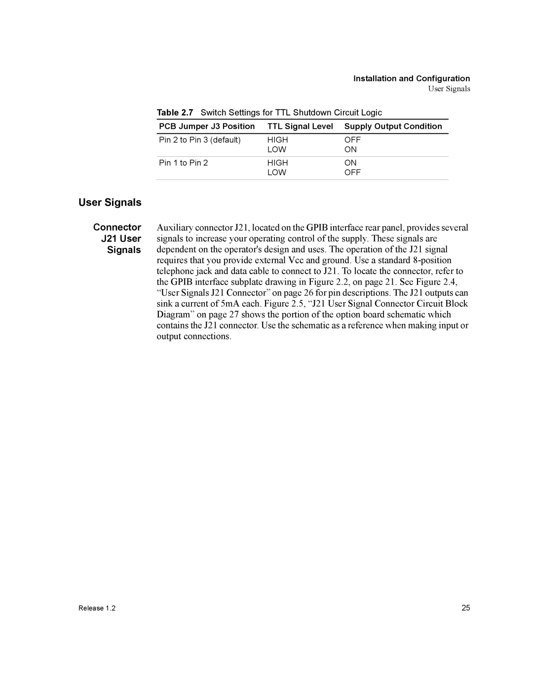
Table 2.7 Switch Settings for TTL Shutdown Circuit Logic

PCB Jumper J3 Position

TTL Signal Level

Supply Output Condition

Pin 2 to Pin 3 (default)

HIGH

OFF


LOW

ON


Pin 1 to Pin 2

HIGH

ON


LOW

OFF

User Signals

Connector Auxiliary connector J21, located on the GPIB interface rear panel, provides several J21 User signals to increase your operating control of the supply. These signals are

Signals dependent on the operator's design and uses. The operation of the J21 signal requires that you provide external Vcc and ground. Use a standard 8-positiontelephone jack and data cable to connect to J21. To locate the connector, refer to the GPIB interface subplate drawing in Figure 2.2, on page 21. See Figure 2.4, “User Signals J21 Connector” on page 26 for pin descriptions. The J21 outputs can sink a current of 5mA each. Figure 2.5, “J21 User Signal Connector Circuit Block Diagram” on page 27 shows the portion of the option board schematic which contains the J21 connector. Use the schematic as a reference when making input or output connections.

Release 1.2

25

Page 27
Image 27
Xantrex Technology GPIB-XPD manual User Signals