Installation and Configuration
User Signals
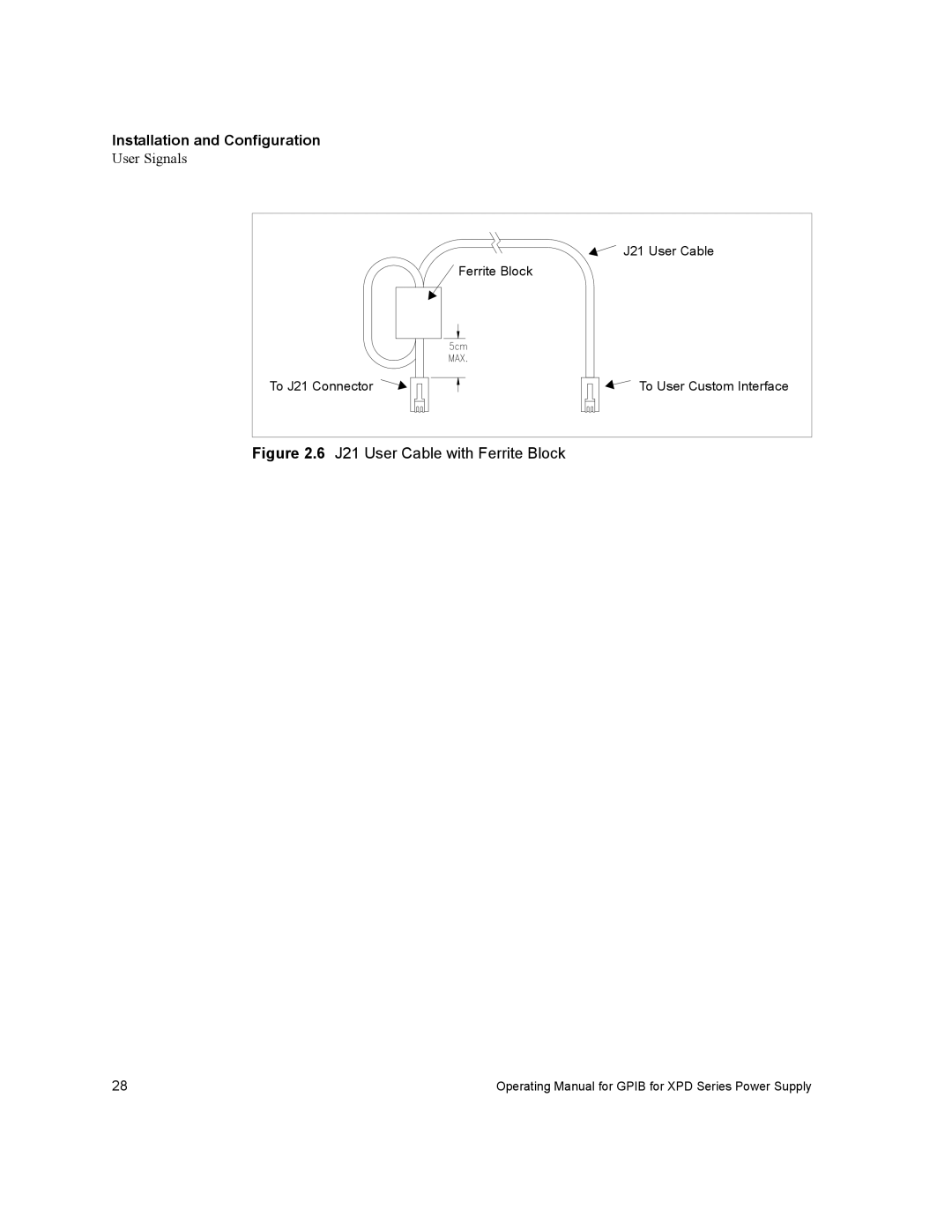
J21 User Cable
![]() Ferrite Block
Ferrite Block
To J21 Connector ![]()
![]()
![]()
![]() To User Custom Interface
To User Custom Interface
Figure 2.6 J21 User Cable with Ferrite Block
28 | Operating Manual for GPIB for XPD Series Power Supply |
User Signals
J21 User Cable
![]() Ferrite Block
Ferrite Block
To J21 Connector ![]()
![]()
![]()
![]() To User Custom Interface
To User Custom Interface
28 | Operating Manual for GPIB for XPD Series Power Supply |