Operation
Command Reference
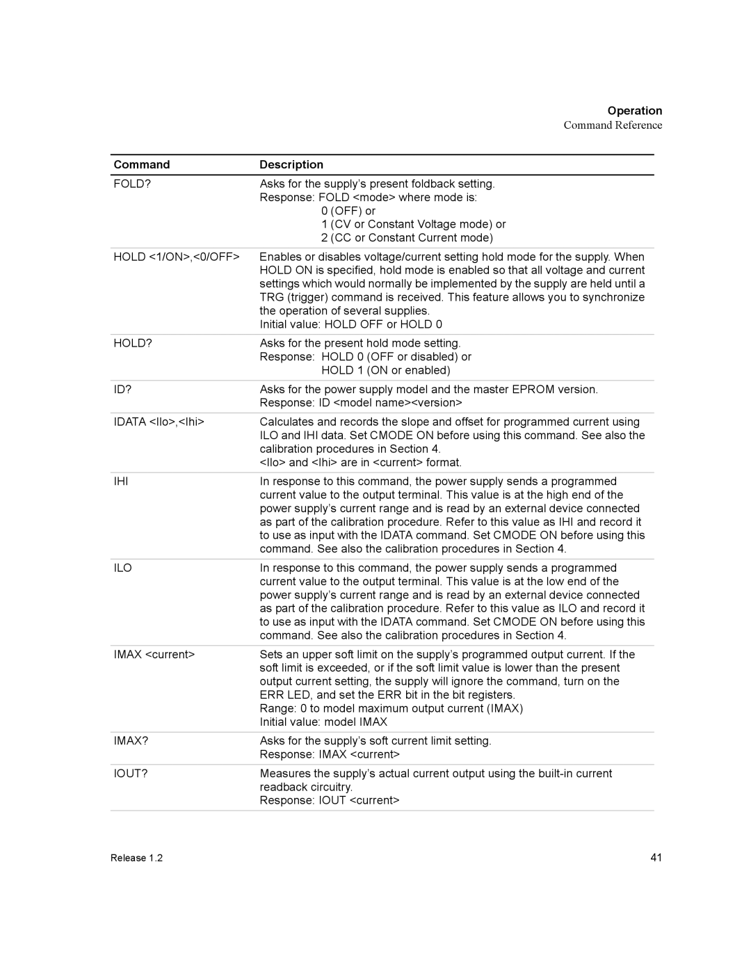
Command | Description |
FOLD? | Asks for the supply’s present foldback setting. |
| Response: FOLD <mode> where mode is: |
| 0 (OFF) or |
| 1 (CV or Constant Voltage mode) or |
| 2 (CC or Constant Current mode) |
HOLD <1/ON>,<0/OFF> | Enables or disables voltage/current setting hold mode for the supply. When |
| HOLD ON is specified, hold mode is enabled so that all voltage and current |
| settings which would normally be implemented by the supply are held until a |
| TRG (trigger) command is received. This feature allows you to synchronize |
| the operation of several supplies. |
| Initial value: HOLD OFF or HOLD 0 |
HOLD? | Asks for the present hold mode setting. |
| Response: HOLD 0 (OFF or disabled) or |
| HOLD 1 (ON or enabled) |
ID? | Asks for the power supply model and the master EPROM version. |
| Response: ID <model name><version> |
IDATA <Ilo>,<Ihi> | Calculates and records the slope and offset for programmed current using |
| ILO and IHI data. Set CMODE ON before using this command. See also the |
| calibration procedures in Section 4. |
| <Ilo> and <Ihi> are in <current> format. |
IHI | In response to this command, the power supply sends a programmed |
| current value to the output terminal. This value is at the high end of the |
| power supply’s current range and is read by an external device connected |
| as part of the calibration procedure. Refer to this value as IHI and record it |
| to use as input with the IDATA command. Set CMODE ON before using this |
| command. See also the calibration procedures in Section 4. |
ILO | In response to this command, the power supply sends a programmed |
| current value to the output terminal. This value is at the low end of the |
| power supply’s current range and is read by an external device connected |
| as part of the calibration procedure. Refer to this value as ILO and record it |
| to use as input with the IDATA command. Set CMODE ON before using this |
| command. See also the calibration procedures in Section 4. |
IMAX <current> | Sets an upper soft limit on the supply’s programmed output current. If the |
| soft limit is exceeded, or if the soft limit value is lower than the present |
| output current setting, the supply will ignore the command, turn on the |
| ERR LED, and set the ERR bit in the bit registers. |
| Range: 0 to model maximum output current (IMAX) |
| Initial value: model IMAX |
IMAX? | Asks for the supply’s soft current limit setting. |
| Response: IMAX <current> |
IOUT? | Measures the supply’s actual current output using the |
| readback circuitry. |
| Response: IOUT <current> |
Release 1.2 | 41 |