Installation Instructions
AC Loads
To install the AC loads:
1.Route the AC load cables through the knockouts in the back of the panel.
2.Install breaker(s) for your AC loads. See the documentation for your breaker to determine how it installs.
3.Connect the hot lead (black) from each AC load to a breaker.
4.Connect the neutral lead (white) from each AC load to the rear AC bus on the panel, marked “AC Neutral Terminal”.
5.Connect the ground lead (green or bare) from each AC load to the front AC bus on the panel, marked “Equipment Grounding Terminal”.
Important: Make a note of which AC load has been connected to which breaker using the provided label on the panel to the side of the breakers. Use pencil in case the circuit is changed in the future.
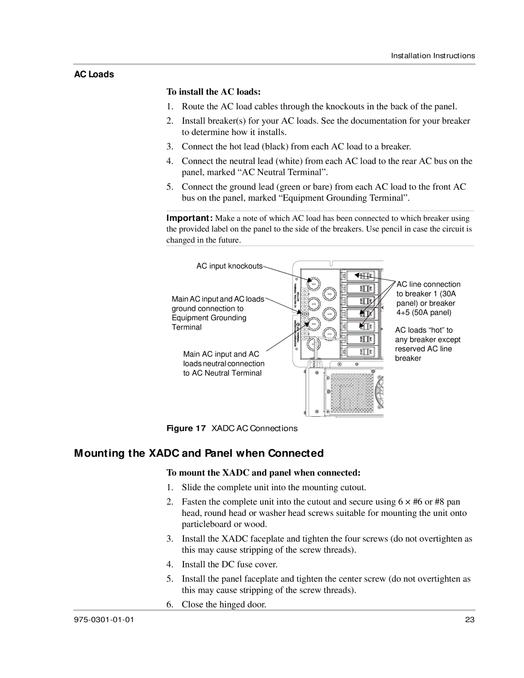
AC input knockouts
Main AC input and AC loads ground connection to Equipment Grounding Terminal
Main AC input and AC loads neutral connection to AC Neutral Terminal
AC line connection to breaker 1 (30A panel) or breaker 4+5 (50A panel)
AC loads “hot” to any breaker except reserved AC line breaker
Figure 17 XADC AC Connections
Mounting the XADC and Panel when Connected
To mount the XADC and panel when connected:
1.Slide the complete unit into the mounting cutout.
2.Fasten the complete unit into the cutout and secure using 6 × #6 or #8 pan head, round head or washer head screws suitable for mounting the unit onto particleboard or wood.
3.Install the XADC faceplate and tighten the four screws (do not overtighten as this may cause stripping of the screw threads).
4.Install the DC fuse cover.
5.Install the panel faceplate and tighten the center screw (do not overtighten as this may cause stripping of the screw threads).
6.Close the hinged door.
23 |