Connecting to System
Xerox FS 3270, User's Guide
2.Installation and Connections of the Xerox FS 3270
This chapter starts with an overview of the functionality of the rear panel. Then follows a description of how you connect the Xerox FS 3270 box to the printerand the system.
NOTE:
Before you start the installation, make sure that you set the rotary switch at the required emulation. See SWITCH B/A/T in section 2.1. below.
2.1. The Rear Panel
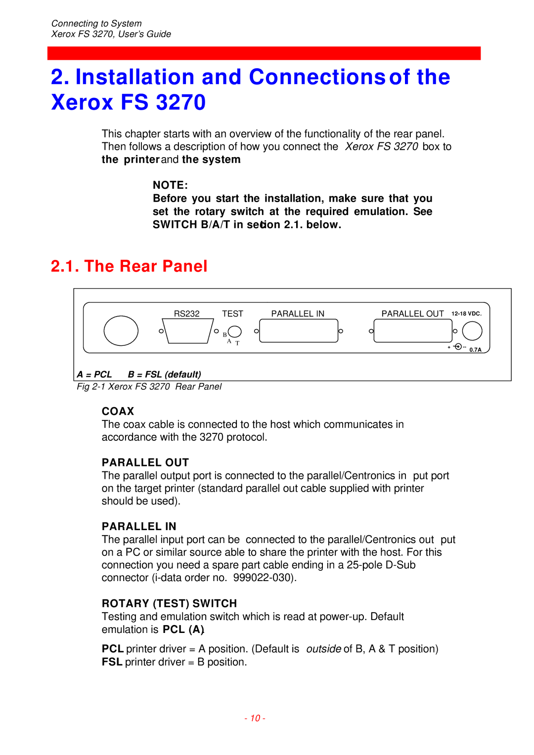
| RS232 | TEST | PARALLEL IN | PARALLEL OUT | |
|
| B |
|
|
|
|
| A T |
| + | |
|
|
|
| ||
A = PCL | B = FSL (default) |
|
|
|
|
Fig
COAX
The coax cable is connected to the host which communicates in accordance with the 3270 protocol.
PARALLEL OUT
The parallel output port is connected to the parallel/Centronics in put port on the target printer (standard parallel out cable supplied with printer should be used).
PARALLEL IN
The parallel input port can be connected to the parallel/Centronics out put on a PC or similar source able to share the printer with the host. For this connection you need a spare part cable ending in a
ROTARY (TEST) SWITCH
Testing and emulation switch which is read at
PCL printer driver = A position. (Default is outside of B, A & T position)
FSL printer driver = B position.
- 10 -