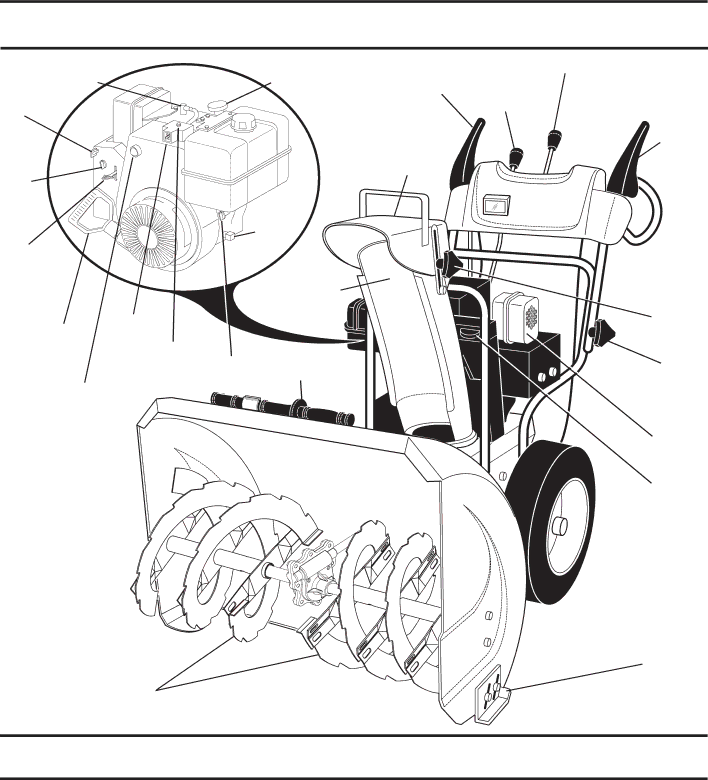
Husqvarna 927SB, 96193004400 owner manual Meets A.N.S.I. Safety Requirements

Page 8

OPERATION

SPARK

PLUG

SAFETY

IGNITION

KEY

CHOKE

CON-

TROL

THROTTLE

/ENGINE

CONTROL

RECOILPOWER

(AUXILIARY) CORD

STARTERPLUG HANDLE

PRIMER

NOTE: ITEMS ABOVE

ARE SHOWN IN

THEIR TYPICAL

LOCATION ON THE

ENGINE. ACTUAL

LOCATION MAY VARY

WITH THE ENGINE

ON YOUR UNIT.

AUGERS

ENGINE OIL CAP

AUGER

WITH DIPSTICK

CONTROL


LEVER

GASOLINE

FILLER

CAP

CHUTE

DEFLECTOR

OIL

DRAIN

PLUG

DISCHARGE

CHUTE

ELECTRICCLEAN-

START FUEL OUT

BUTTON SHUT-OFF TOOL

VALVE

FIG. 8

DISCHARGE CHUTE

DRIVE CONTROL LEVER

SPEED

CONTROL

LEVER

TRACTION

DRIVE

CONTROL

LEVER

CHUTE

DEFLECTOR

KNOB

HANDLE

KNOB

MUFFLER

TOOLBOX

SKID PLATE

MEETS A.N.S.I. SAFETY REQUIREMENTS

Our snow throwers conform to the standards of the American National Standards Institute.

Toolbox - used to store spare shear bolts, locknuts and wrench.

Safety ignition key - must be inserted for the engine to start and run. Remove when snow thrower is not in use.

Electric start button - used for starting the engine.


Recoil (auxiliary) starter handle - used for starting the


engine.


Primer - pumps additional fuel from the carburetor to the


cylinder for use when starting a cold engine.


Choke control - used for starting a cold engine.


Drive speed control lever - used to select forward or

8

reverse motion and speed of snow thrower.

Throttle/engine control - used to select either FAST or SLOW engine speed and to STOP the engine.

Traction drive control lever - used to engage power-pro- pelled forward or reverse motion of snow thrower.

Auger control lever - used to engage auger motion (throw snow).

Discharge chute control lever - used to change the direc- tion the snow is thrown.

Skid plate - used to adjust height of scraper bar from the ground.

Image 8
Contents 927SB Safe Operation Practices for Walk-Behind Snow Throwers Table of Contents Assembly / PRE-OPERATION HOW to SET UP Your Snow ThrowerParts Packed Separately in Carton Remove Snow Thrower from CartonUnfold Upper Handle Install Speed Control ROD See FigsInstall Traction Drive Control ROD See Figs Install Auger Control ROD See Figs Install Discharge Chute / Chute Rotator Head See FigOperation Know Your Snow ThrowerPrimer Ignition KEYDrive speed control lever used to select forward or Meets A.N.S.I. Safety RequirementsRecoil auxiliary starter handle used for starting HOW to USE Your Snow Thrower StoppingWhen traction drive control lever is engaged Using the CLEAN-OUT Tool See FigTo Move Forward and Backward See Fig To Throw Snow See FigTo Adjust Skid Plates See Fig Before Starting the EngineScraper BAR See Fig Check Engine OIL Level See FigSnow Throwing Tips To Start EngineBefore Stopping If Recoil Starter has FrozenMaintenance Cleaning EngineService and Adjustments To Adjust Snow Thrower HeightChute Deflector Shear Bolts See FigTo Replace Belts See Fig Storage CarburetorEngine Speed Fuel SystemOther CylinderTroubleshooting Auger Housing / Impeller Assembly KEY Part DescriptionScraper BAR Auger BearingAuger 27 LH Auger 27 RHExploded 532 19 67-10 Gearbox Assembly ImpellerBearing Tool ClipRepair Parts 532 18 41-13 Deflector WeldmentStrap Knob BlackControl Panel / Discharge Chute Handles 532 42 14-48 Headlight Bezel GrayBulb Lower Tube01.08.004-B Spacer RetainerKnob RED Handle Knob532 18 04-80 Impeller ROD Assembly 532 40 57-40 Traction ROD AssemblyClutch ROD Rear PlateDrive 532 17 53-44 Trunnion Bearing Assembly Control Shaft AssemblyHEX Shaft Pinion Gear3534 Assembly 532 18 40-74 Idler Pivot Bracket Assembly 532 17 93-54 Idler Traction ARM532 19 84-74 Speed Selector Head Idler PulleyAxle Shaft Roll PIN 3/16Gear Clik PINBottom PAN ENGINE, TECFrame Impeller Belt Chassis / Engine / PulleysPulley Wheel Assembly LH WheelsPower Cord KEY Part Description 532 03 50-62 Safety Ignition KEYBAG of Parts Retainer PINDecals 532 18 10-35 DECAL, DANGER, DeflectorWarranty Statement