Husqvarna 96193004400, 927SB owner manual Maintenance

Page 13

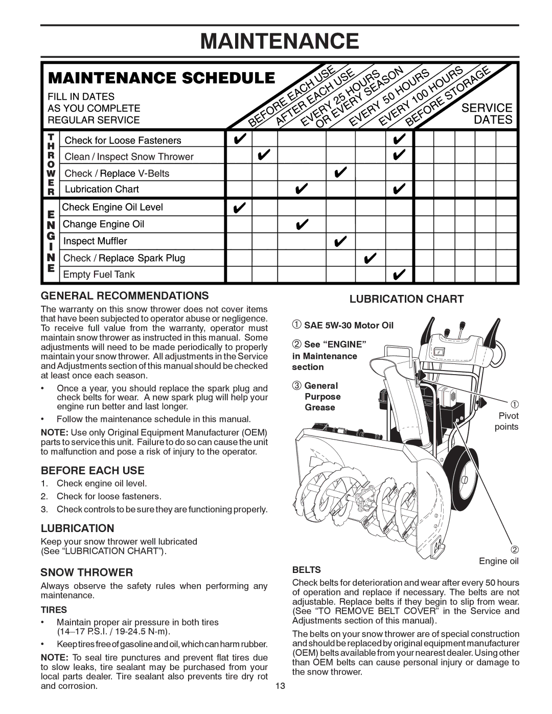
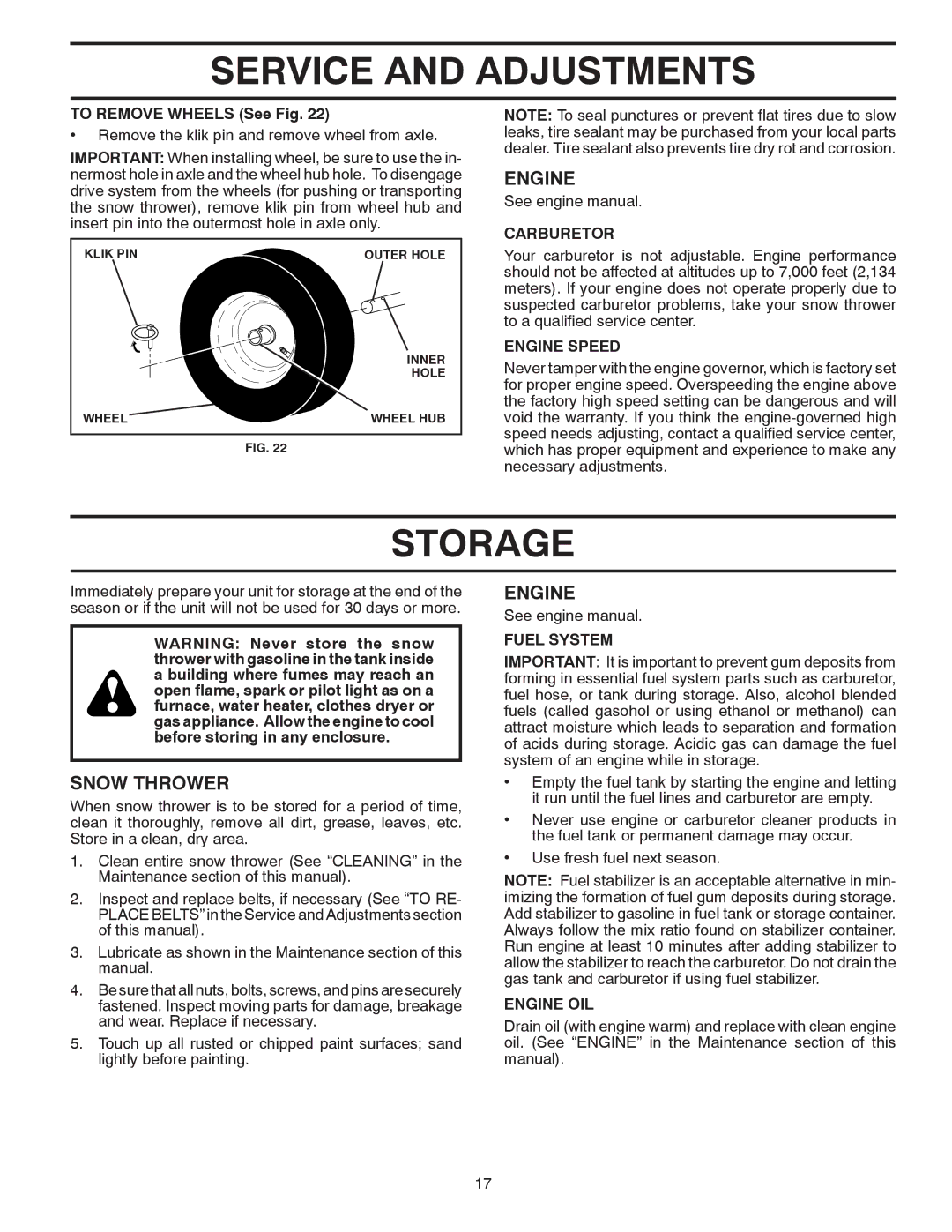
MAINTENANCE

GENERAL RECOMMENDATIONS

The warranty on this snow thrower does not cover items that have been subjected to operator abuse or negligence. To receive full value from the warranty, operator must maintain snow thrower as instructed in this manual. Some adjustments will need to be made periodically to properly maintain your snow thrower. All adjustments in the Service and Adjustments section of this manual should be checked at least once each season.

Once a year, you should replace the spark plug and check belts for wear. A new spark plug will help your engine run better and last longer.

Follow the maintenance schedule in this manual.

NOTE: Use only Original Equipment Manufacturer (OEM) parts to service this unit. Failure to do so can cause the unit to malfunction and pose a risk of injury to the operator.

BEFORE EACH USE

1.Check engine oil level.

2.Check for loose fasteners.

3.Check controls to be sure they are functioning properly.

LUBRICATION

Keep your snow thrower well lubricated (See “LUBRICATION CHART”).

SNOW THROWER

Always observe the safety rules when performing any maintenance.

TIRES

Maintain proper air pressure in both tires (14–17 P.S.I. / 19-24.5 N-m).

Keeptiresfreeofgasolineandoil,whichcanharmrubber.

NOTE: To seal tire punctures and prevent flat tires due


to slow leaks, tire sealant may be purchased from your


local parts dealer. Tire sealant also prevents tire dry rot

13

and corrosion.

LUBRICATION CHART

SAE 5W-30 Motor Oil

See “ENGINE” in Maintenance section

General

Purpose

Grease

Pivot points

Engine oil

BELTS

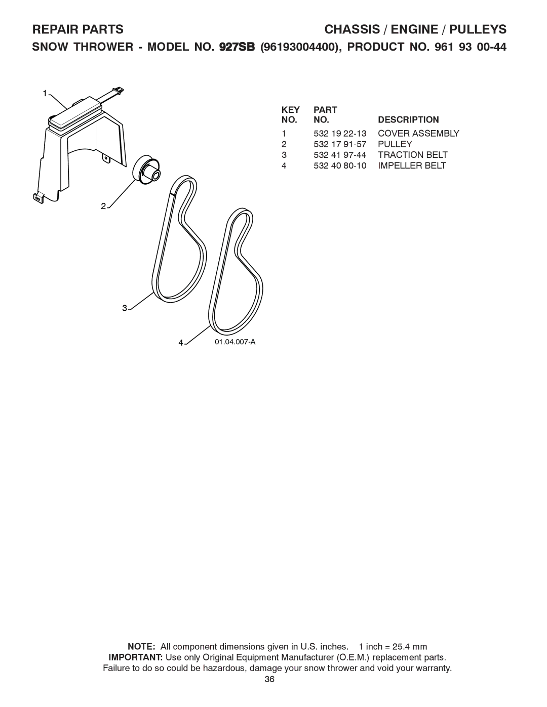
Check belts for deterioration and wear after every 50 hours of operation and replace if necessary. The belts are not adjustable. Replace belts if they begin to slip from wear. (See “TO REMOVE BELT COVER” in the Service and Adjustments section of this manual).

The belts on your snow thrower are of special construction and should be replaced by original equipment manufacturer (OEM) belts available from your nearest dealer. Using other than OEM belts can cause personal injury or damage to the snow thrower.
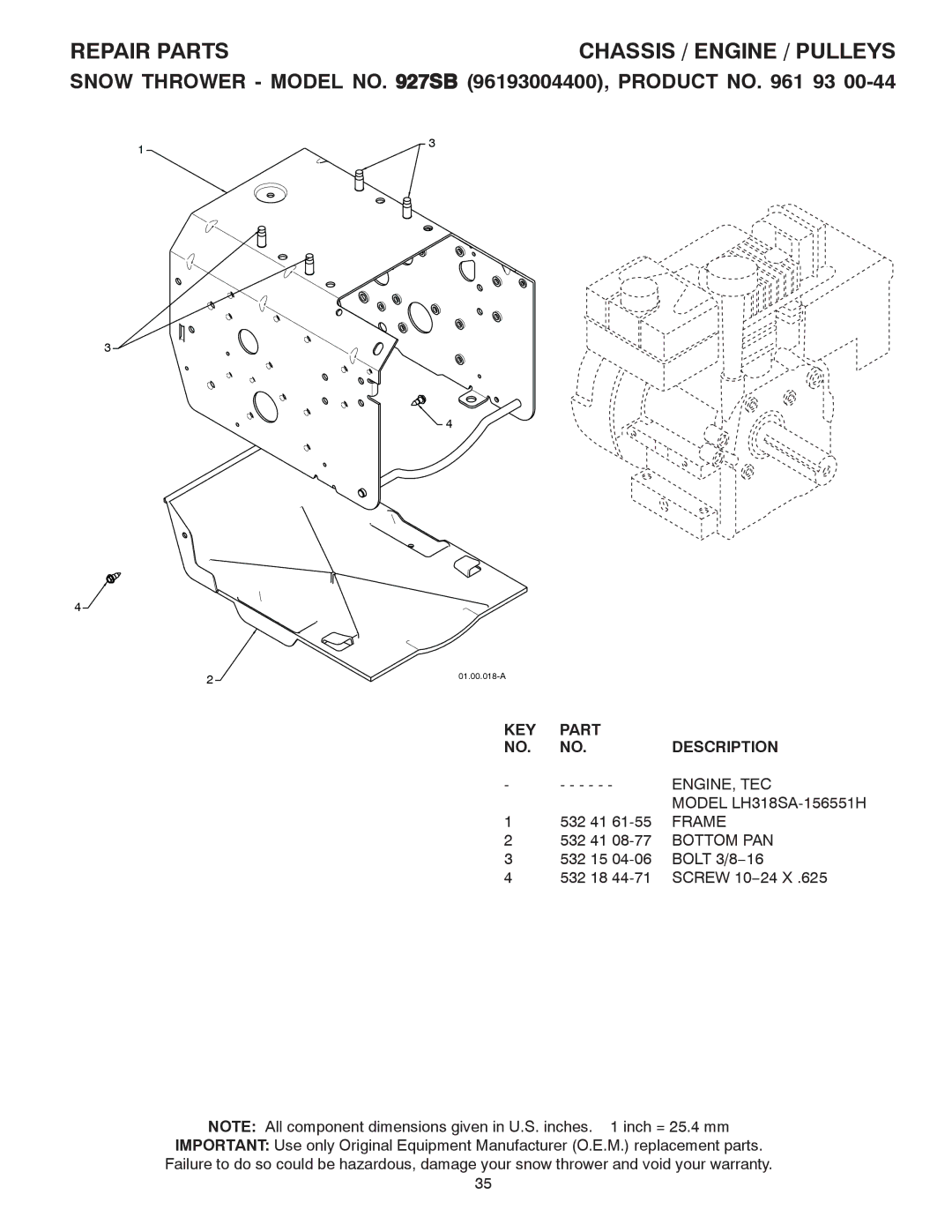
Image 13
Contents 927SB Safe Operation Practices for Walk-Behind Snow Throwers Table of Contents HOW to SET UP Your Snow Thrower Assembly / PRE-OPERATIONParts Packed Separately in Carton Remove Snow Thrower from CartonInstall Traction Drive Control ROD See Figs Install Speed Control ROD See FigsUnfold Upper Handle Install Discharge Chute / Chute Rotator Head See Fig Install Auger Control ROD See FigsKnow Your Snow Thrower OperationPrimer Ignition KEYRecoil auxiliary starter handle used for starting Meets A.N.S.I. Safety RequirementsDrive speed control lever used to select forward or Stopping HOW to USE Your Snow ThrowerUsing the CLEAN-OUT Tool See Fig When traction drive control lever is engagedTo Move Forward and Backward See Fig To Throw Snow See FigBefore Starting the Engine To Adjust Skid Plates See FigScraper BAR See Fig Check Engine OIL Level See FigTo Start Engine Snow Throwing TipsBefore Stopping If Recoil Starter has FrozenMaintenance Engine CleaningTo Adjust Snow Thrower Height Service and AdjustmentsChute Deflector Shear Bolts See FigTo Replace Belts See Fig Carburetor StorageEngine Speed Fuel SystemCylinder OtherTroubleshooting KEY Part Description Auger Housing / Impeller AssemblyScraper BAR Auger BearingAuger 27 RH Auger 27 LHExploded Impeller 532 19 67-10 Gearbox AssemblyBearing Tool Clip532 18 41-13 Deflector Weldment Repair PartsStrap Knob BlackControl Panel / Discharge Chute 532 42 14-48 Headlight Bezel Gray HandlesBulb Lower Tube01.08.004-B Retainer SpacerKnob RED Handle Knob532 40 57-40 Traction ROD Assembly 532 18 04-80 Impeller ROD AssemblyClutch ROD Rear PlateDrive Control Shaft Assembly 532 17 53-44 Trunnion Bearing AssemblyHEX Shaft Pinion Gear3534 Assembly 532 17 93-54 Idler Traction ARM Assembly 532 18 40-74 Idler Pivot Bracket532 19 84-74 Speed Selector Head Idler PulleyRoll PIN 3/16 Axle ShaftGear Clik PINFrame ENGINE, TECBottom PAN Pulley Chassis / Engine / PulleysImpeller Belt Wheels Wheel Assembly LHKEY Part Description 532 03 50-62 Safety Ignition KEY Power CordBAG of Parts Retainer PIN532 18 10-35 DECAL, DANGER, Deflector DecalsWarranty Statement