Orion Car Audio 1892 1335 manual Operation, LED Indications

Page 22

OPERATION

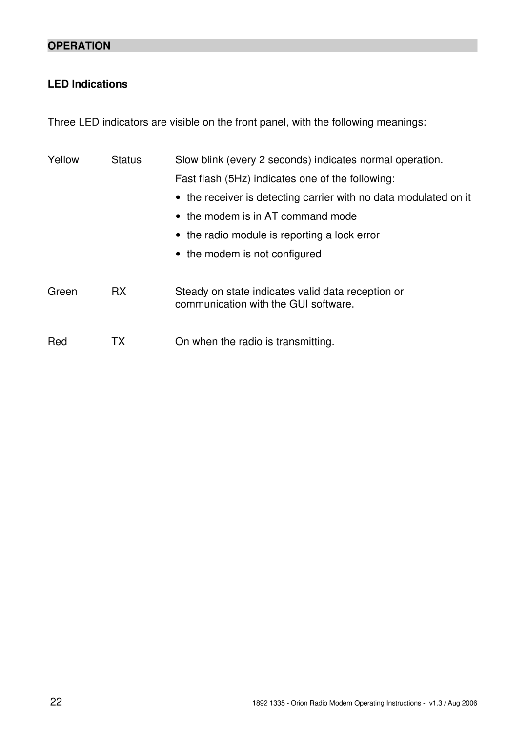
LED Indications

Three LED indicators are visible on the front panel, with the following meanings:

Yellow

Status

Slow blink (every 2 seconds) indicates normal operation.


Fast flash (5Hz) indicates one of the following:


v the receiver is detecting carrier with no data modulated on it


v the modem is in AT command mode


v the radio module is reporting a lock error


v the modem is not configured

Green

RX

Steady on state indicates valid data reception or


communication with the GUI software.

Red

TX

On when the radio is transmitting.

22

1892 1335 - Orion Radio Modem Operating Instructions - v1.3 / Aug 2006

Image 22
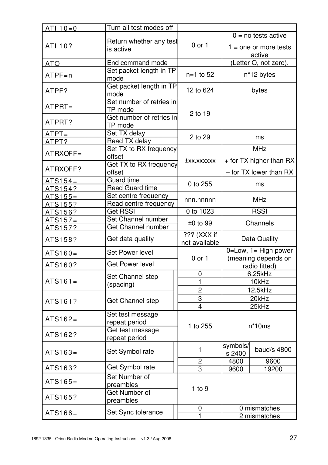
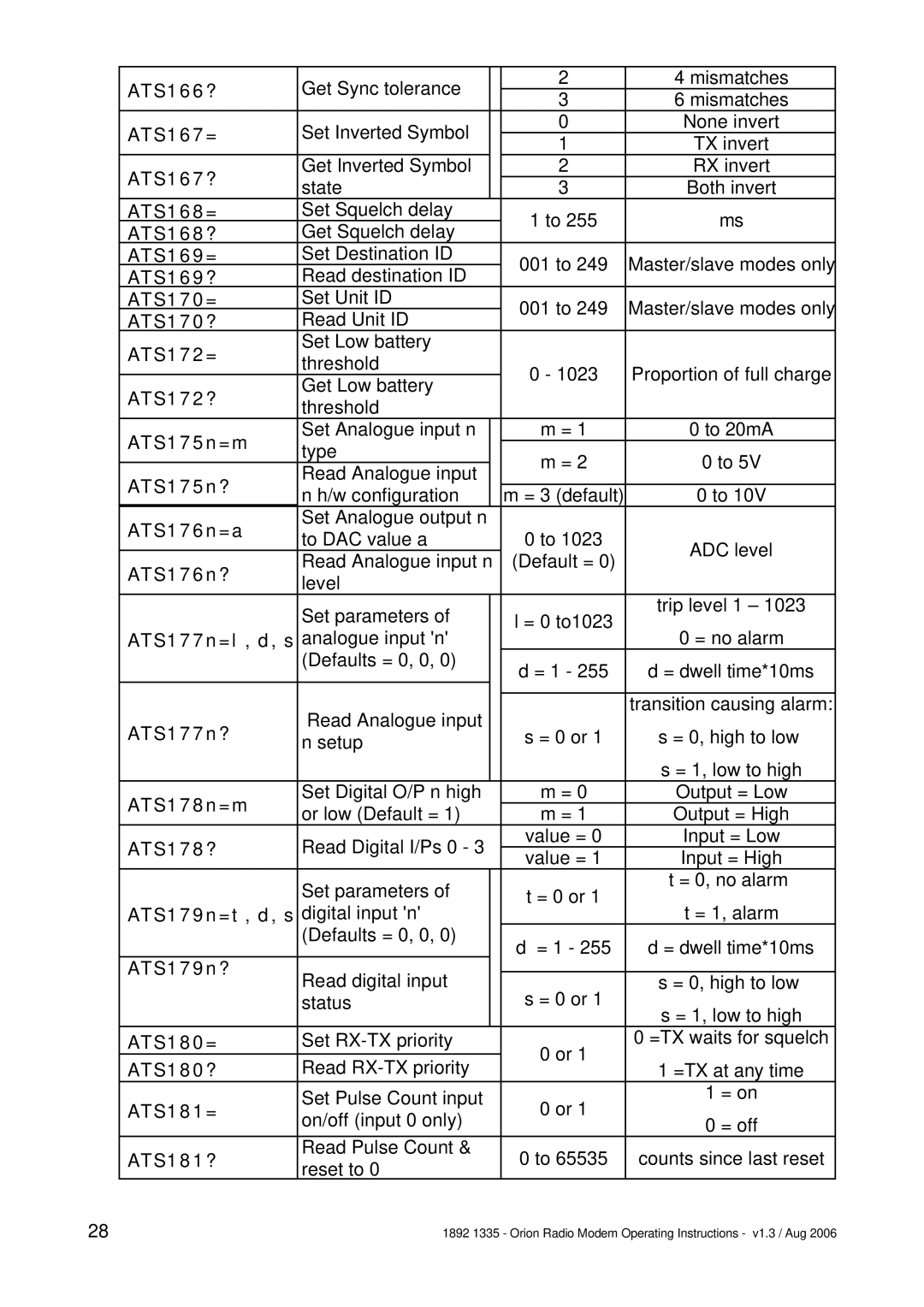
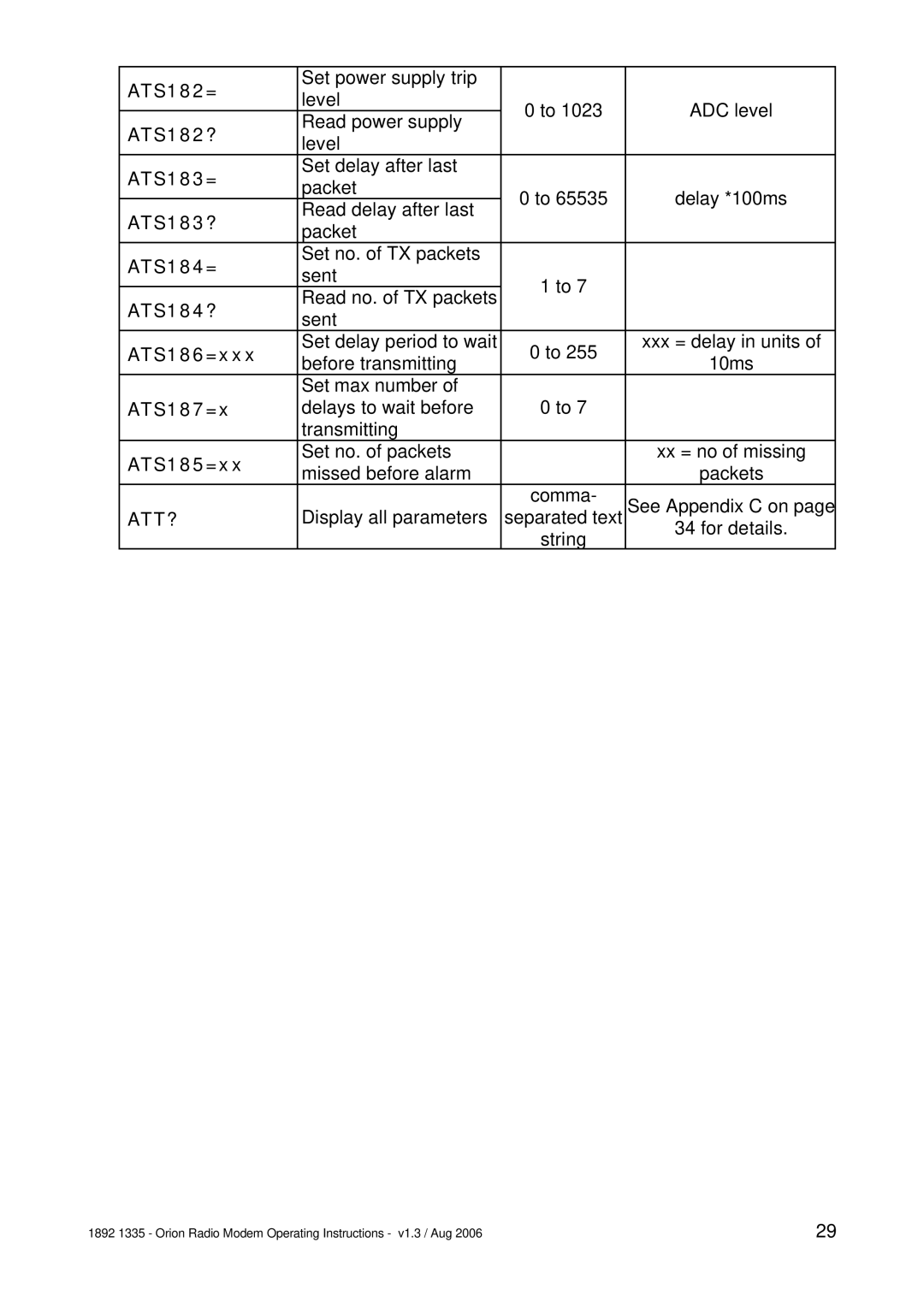
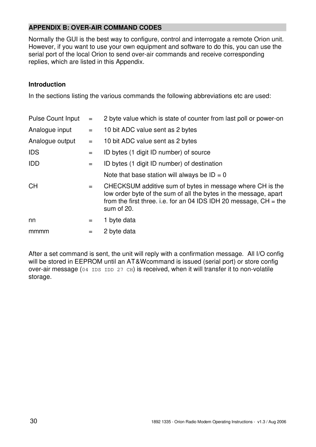
Contents Orion Radio Modem with I/O Operating Instructions Orion Radio ModemShows the Orion in block diagram form OverviewPage Options When Ordering Installation PhysicalDimensions of Orion PCB mm Connections RJ45 Port Pin No Digital Digital Out Analogue Analogue OutPin No RS232 RS422 RS485 TXBGraphical User Interface GUI Setting UP AN Orion Hardware Link SettingsUsing the GUI Option Choice LinksPage COM Ports and General Status Modem Modes TRR TSR TUR TMR TNT TMX TNX TOM TOSModem Parameter Configuration TOR TOT TOX TOTPage This space reserved for additional material Telemetry Option Configuration Analogue In Set-upAlarms This space reserved for additional material Operation LED IndicationsAppendix a AT Command Codes Wait+++waitenterCommand Syntax ATS154=Start Command Mode Wait period set by ATS154= Ending Command Mode ATOCommands Description Values End Command Mode Letter 0, not zeroAT&W AT&F=AT&F? AT&Y8ATPRT? ATPF?ATPRT= ATPT=ATS167? ATS166?ATS167= ATS168=ATT? Appendix B OVER-AIR Command Codes IntroductionMessages from Base Station to Outstation IDS IDD 20 CHIDS IDD 45 CH Messages from Outstation to Base Station IDS IDD 51 nn tt dd ss CHIDS IDD 65 nn cccc CH Page Appendix C ATT? Parameter String Structure