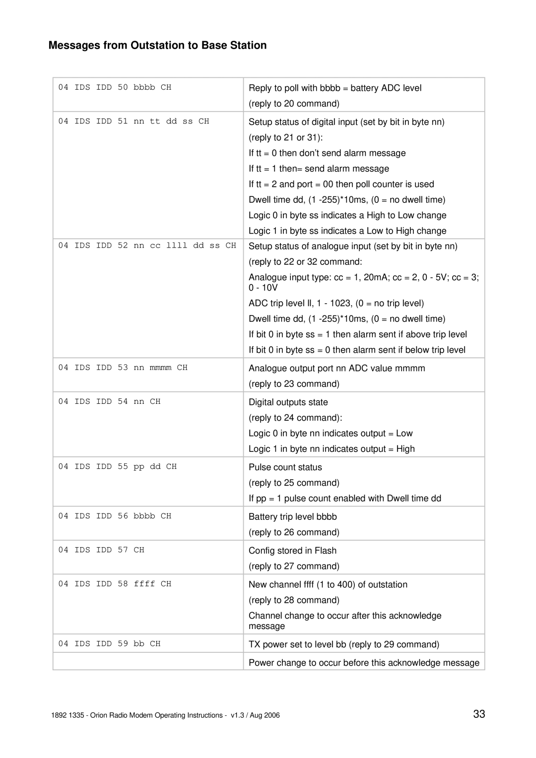
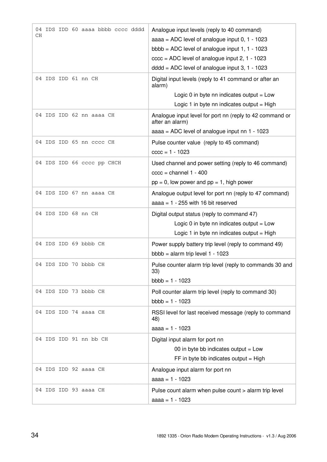
Messages from Outstation to Base Station
04 | IDS IDD 50 bbbb CH | Reply to poll with bbbb = battery ADC level |
|
| (reply to 20 command) |
|
|
|
04 | IDS IDD 51 nn tt dd ss CH | Setup status of digital input (set by bit in byte nn) |
|
| (reply to 21 or 31): |
|
| If tt = 0 then don’t send alarm message |
|
| If tt = 1 then= send alarm message |
|
| If tt = 2 and port = 00 then poll counter is used |
|
| Dwell time dd, (1 |
|
| Logic 0 in byte ss indicates a High to Low change |
|
| Logic 1 in byte ss indicates a Low to High change |
|
|
|
04 | IDS IDD 52 nn cc llll dd ss CH | Setup status of analogue input (set by bit in byte nn) |
|
| (reply to 22 or 32 command: |
|
| Analogue input type: cc = 1, 20mA; cc = 2, 0 - 5V; cc = 3; |
|
| 0 - 10V |
|
| ADC trip level ll, 1 - 1023, (0 = no trip level) |
|
| Dwell time dd, (1 |
|
| If bit 0 in byte ss = 1 then alarm sent if above trip level |
|
| If bit 0 in byte ss = 0 then alarm sent if below trip level |
|
|
|
04 | IDS IDD 53 nn mmmm CH | Analogue output port nn ADC value mmmm |
|
| (reply to 23 command) |
|
|
|
04 | IDS IDD 54 nn CH | Digital outputs state |
|
| (reply to 24 command): |
|
| Logic 0 in byte nn indicates output = Low |
|
| Logic 1 in byte nn indicates output = High |
|
|
|
04 | IDS IDD 55 pp dd CH | Pulse count status |
|
| (reply to 25 command) |
|
| If pp = 1 pulse count enabled with Dwell time dd |
|
|
|
04 | IDS IDD 56 bbbb CH | Battery trip level bbbb |
|
| (reply to 26 command) |
|
|
|
04 | IDS IDD 57 CH | Config stored in Flash |
|
| (reply to 27 command) |
|
|
|
04 | IDS IDD 58 ffff CH | New channel ffff (1 to 400) of outstation |
|
| (reply to 28 command) |
|
| Channel change to occur after this acknowledge |
|
| message |
|
|
|
04 | IDS IDD 59 bb CH | TX power set to level bb (reply to 29 command) |
|
|
|
|
| Power change to occur before this acknowledge message |
|
|
|
1892 1335 - Orion Radio Modem Operating Instructions - v1.3 / Aug 2006 | 33 |
