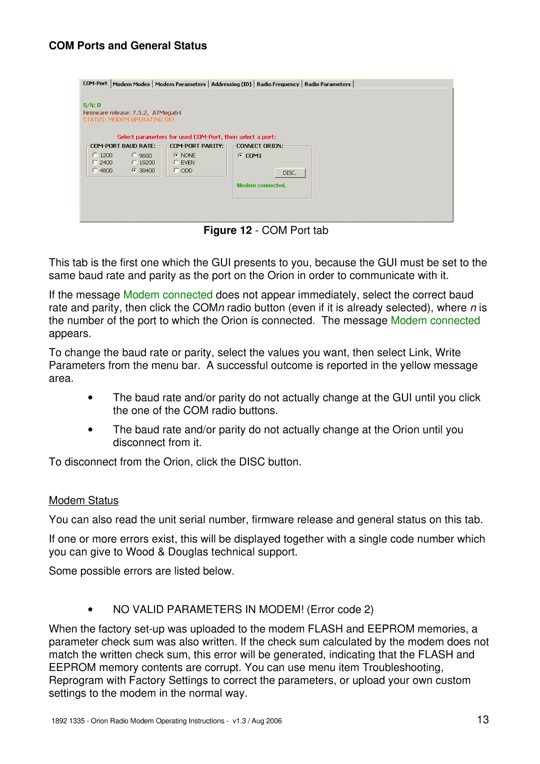
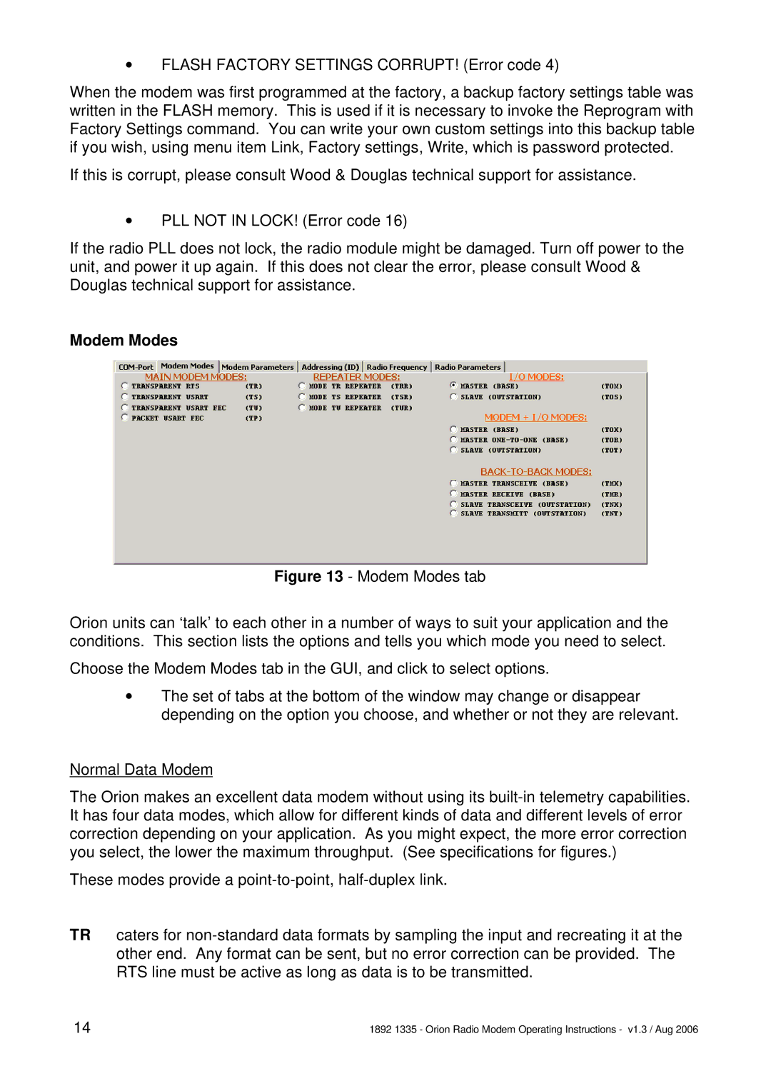
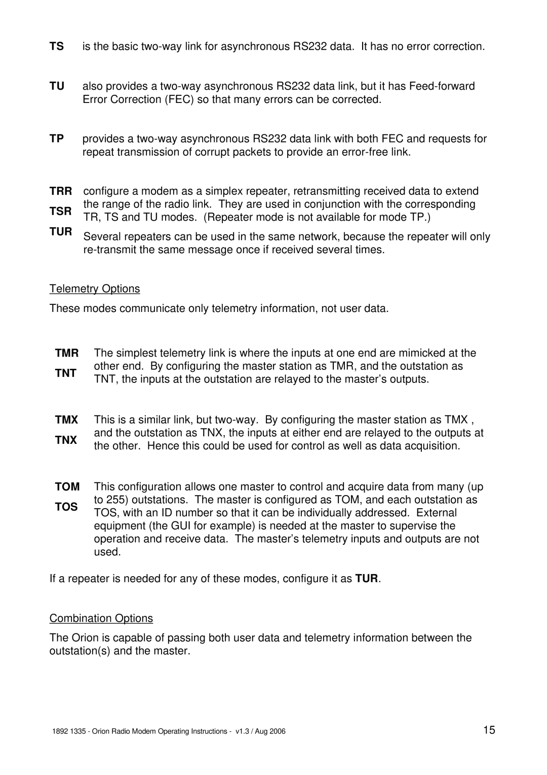
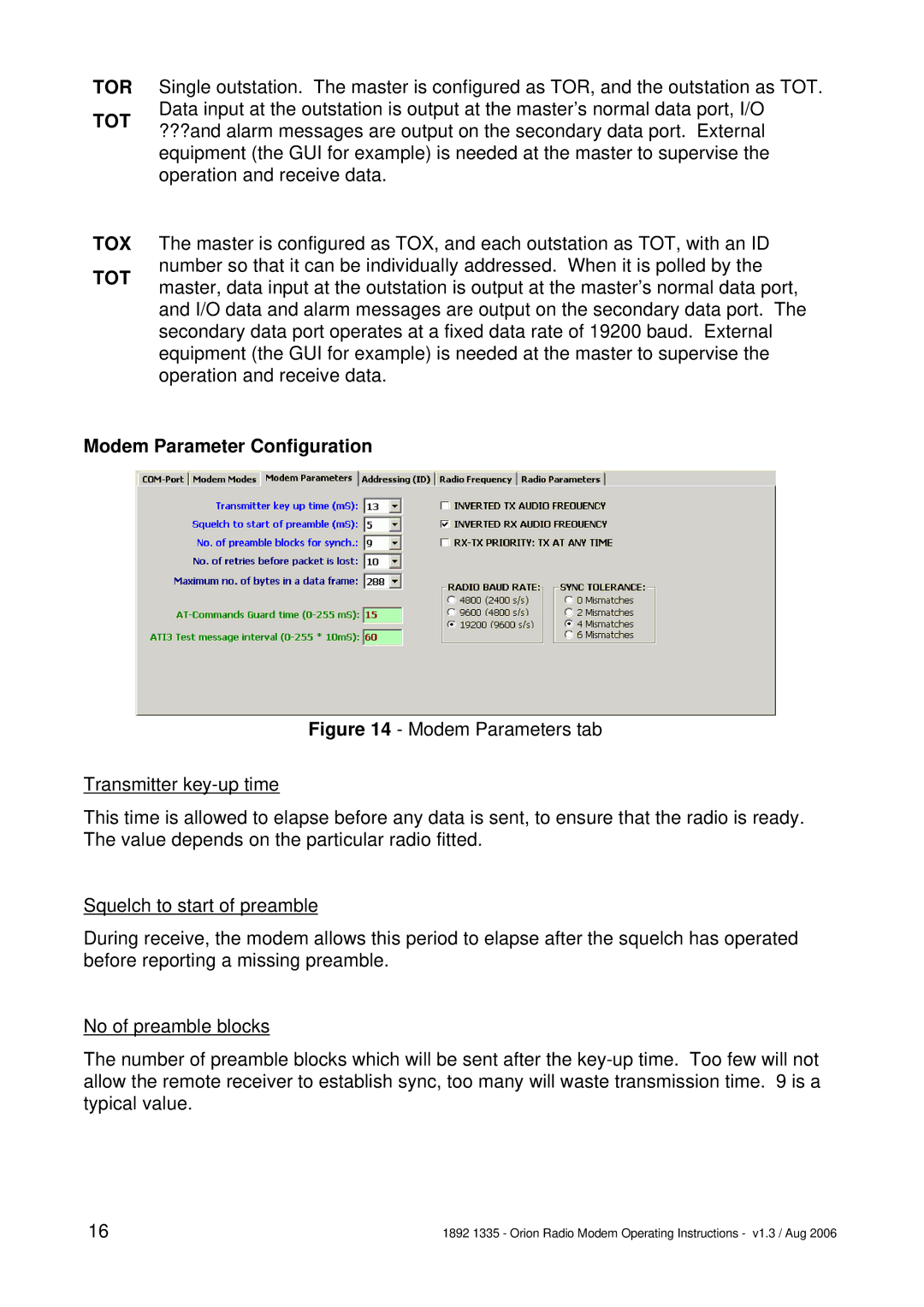
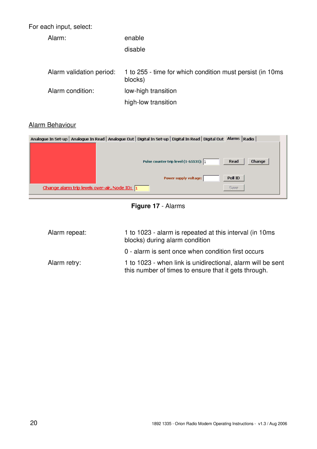
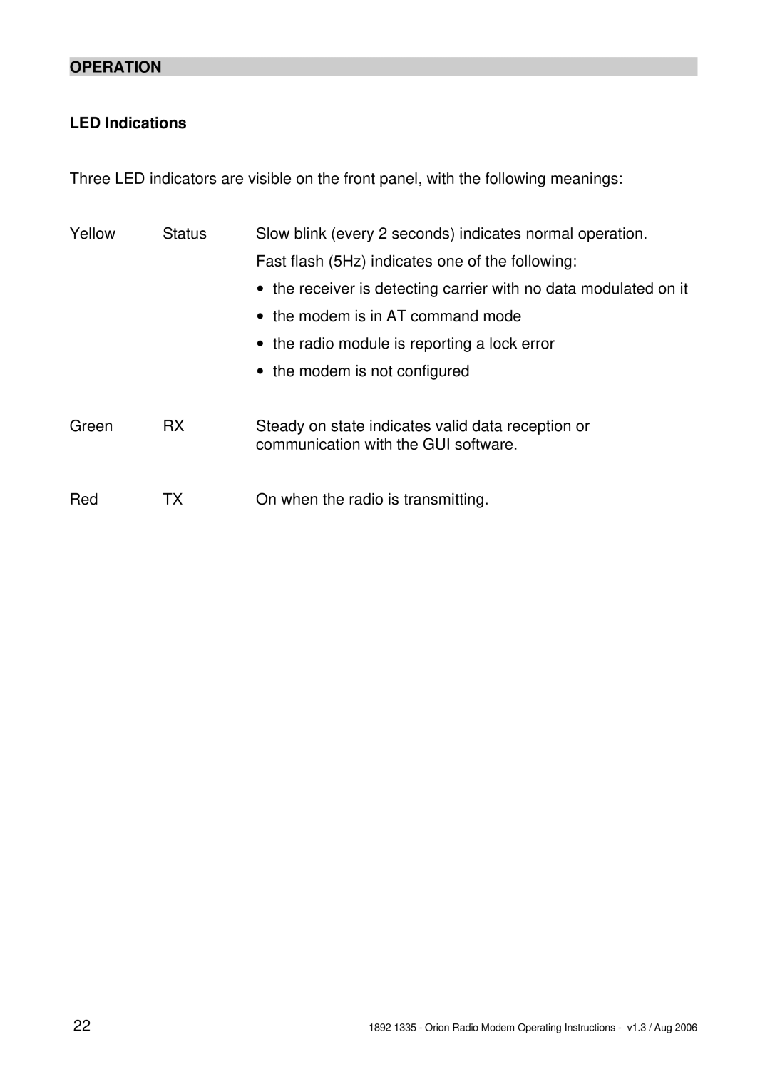
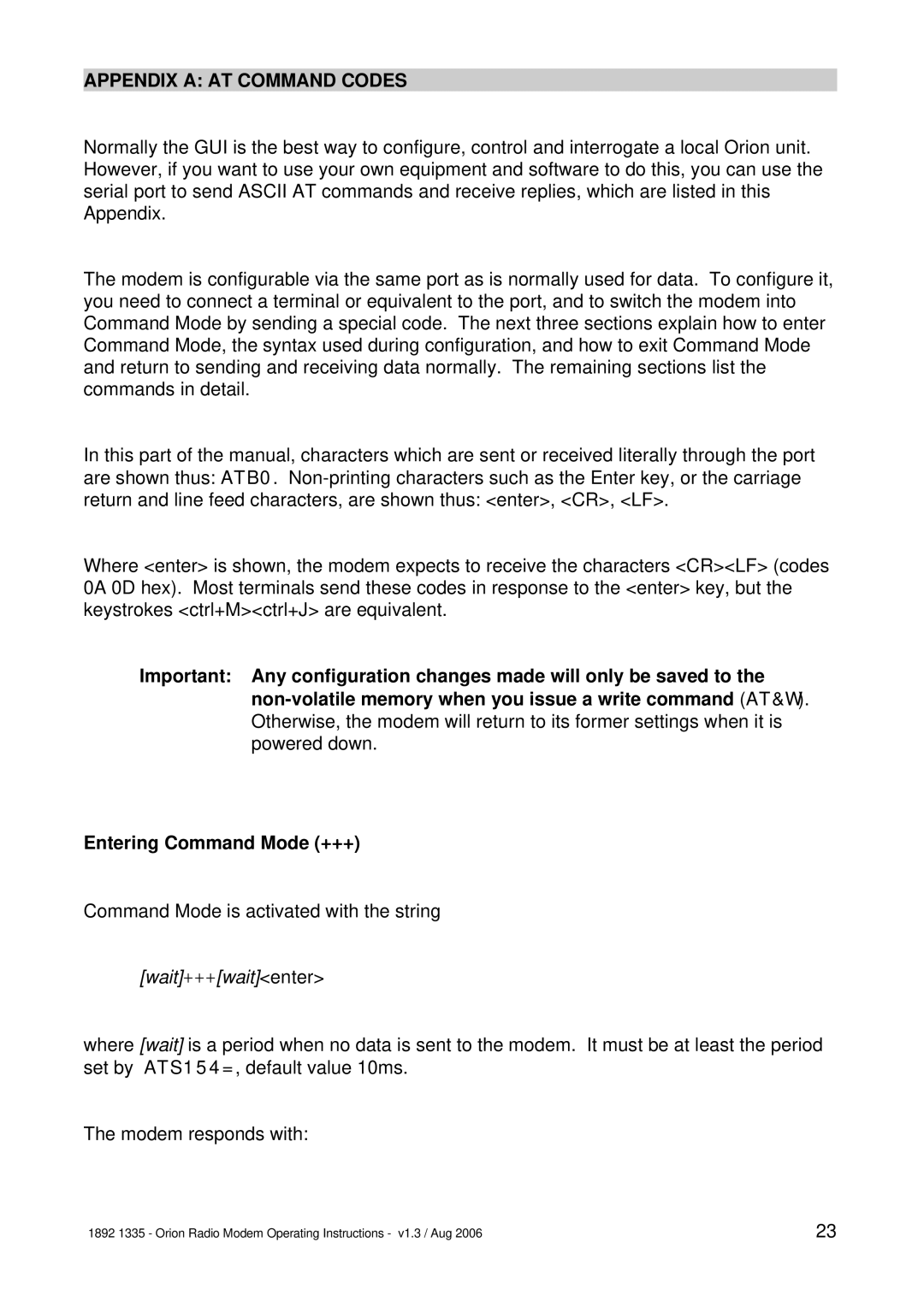
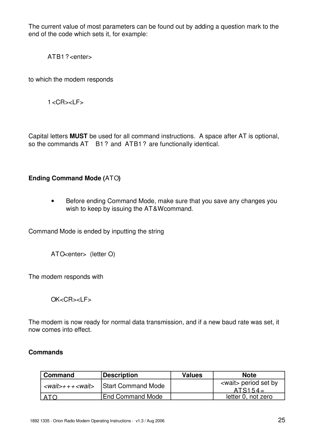
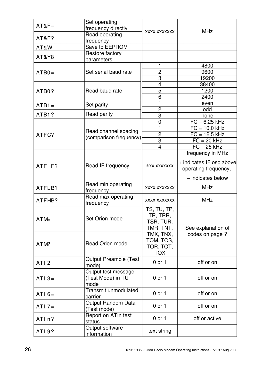
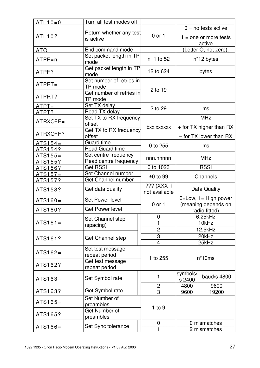
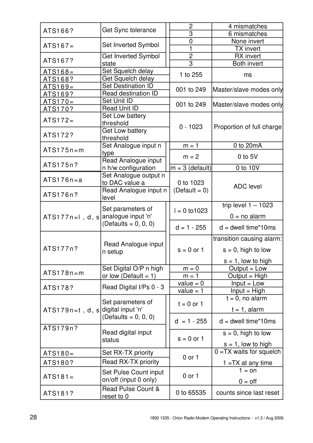
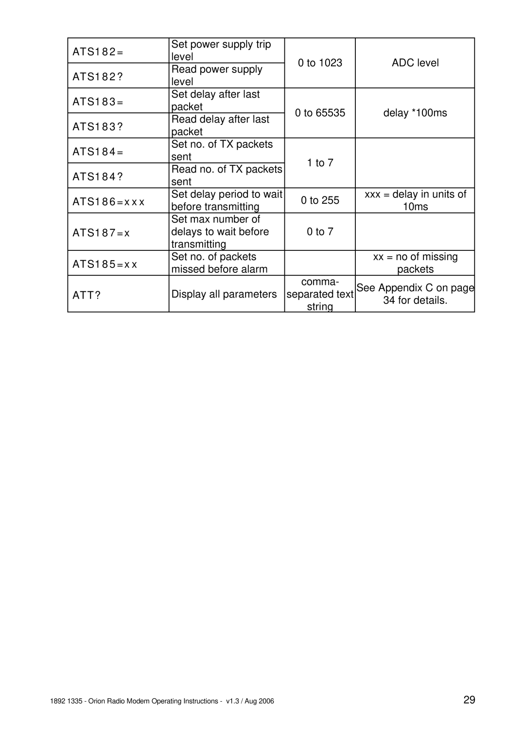
Orion Car Audio 1892 1335 manual Trr Tsr Tur, Tmr Tnt Tmx Tnx Tom Tos

Page 15

TS

TU

TP

TRR TSR TUR

is the basic two-way link for asynchronous RS232 data. It has no error correction.

also provides a two-way asynchronous RS232 data link, but it has Feed-forward Error Correction (FEC) so that many errors can be corrected.

provides a two-way asynchronous RS232 data link with both FEC and requests for repeat transmission of corrupt packets to provide an error-free link.

configure a modem as a simplex repeater, retransmitting received data to extend the range of the radio link. They are used in conjunction with the corresponding TR, TS and TU modes. (Repeater mode is not available for mode TP.)

Several repeaters can be used in the same network, because the repeater will only re-transmit the same message once if received several times.

Telemetry Options

These modes communicate only telemetry information, not user data.

TMR TNT

TMX TNX

TOM TOS

The simplest telemetry link is where the inputs at one end are mimicked at the other end. By configuring the master station as TMR, and the outstation as TNT, the inputs at the outstation are relayed to the master’s outputs.

This is a similar link, but two-way. By configuring the master station as TMX , and the outstation as TNX, the inputs at either end are relayed to the outputs at the other. Hence this could be used for control as well as data acquisition.

This configuration allows one master to control and acquire data from many (up to 255) outstations. The master is configured as TOM, and each outstation as TOS, with an ID number so that it can be individually addressed. External equipment (the GUI for example) is needed at the master to supervise the operation and receive data. The master’s telemetry inputs and outputs are not used.

If a repeater is needed for any of these modes, configure it as TUR.

Combination Options

The Orion is capable of passing both user data and telemetry information between the outstation(s) and the master.

1892 1335 - Orion Radio Modem Operating Instructions - v1.3 / Aug 2006

15

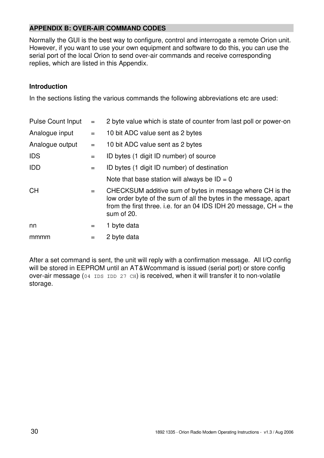
Image 15
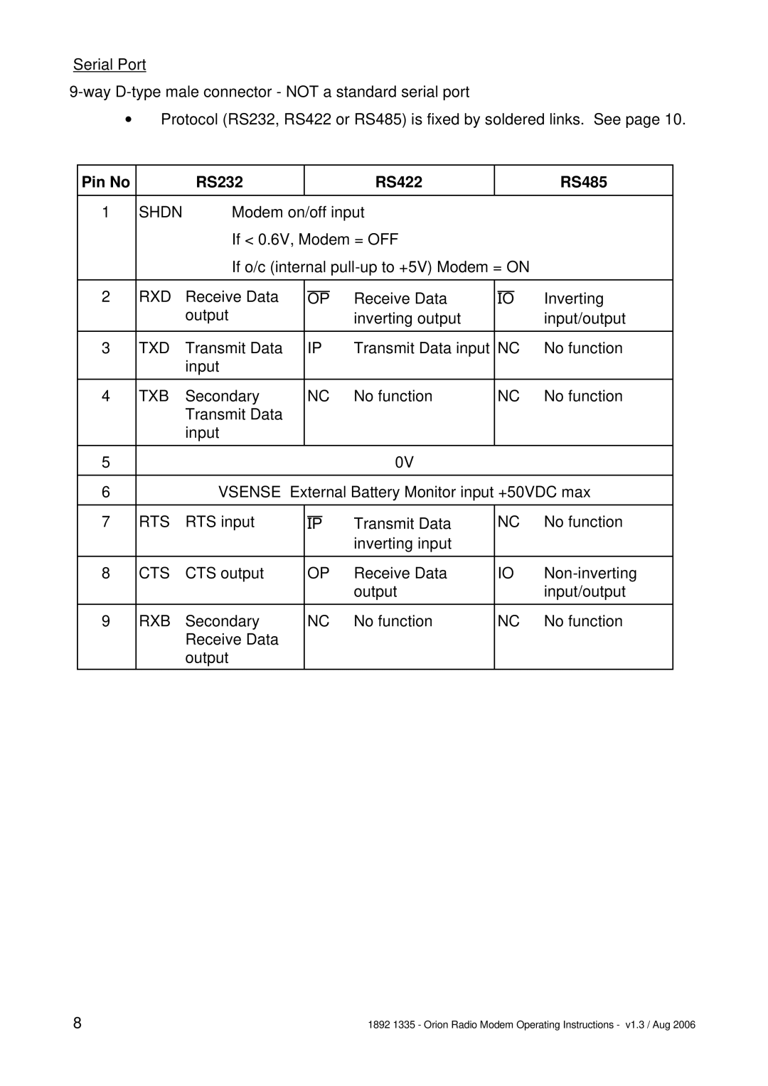
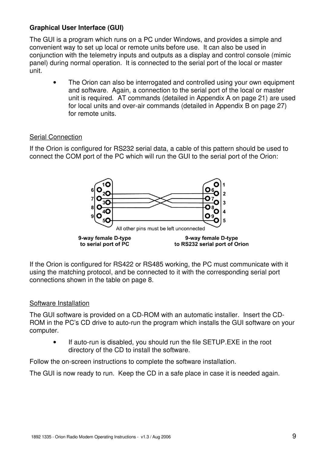
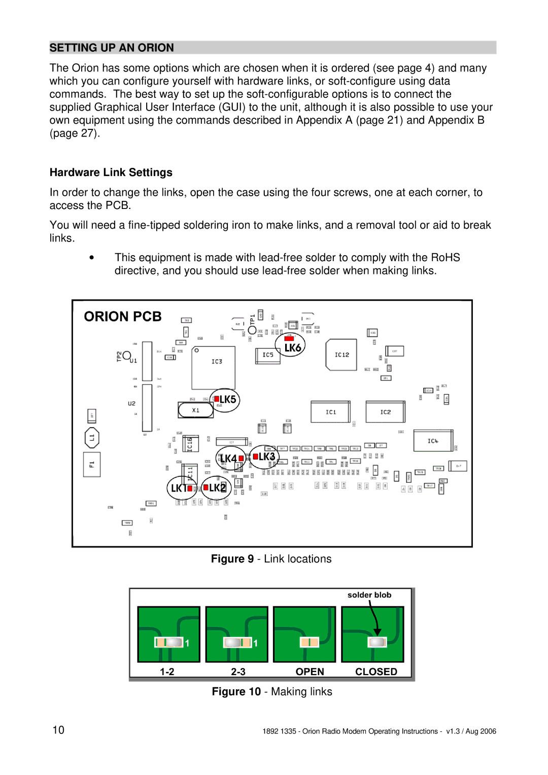
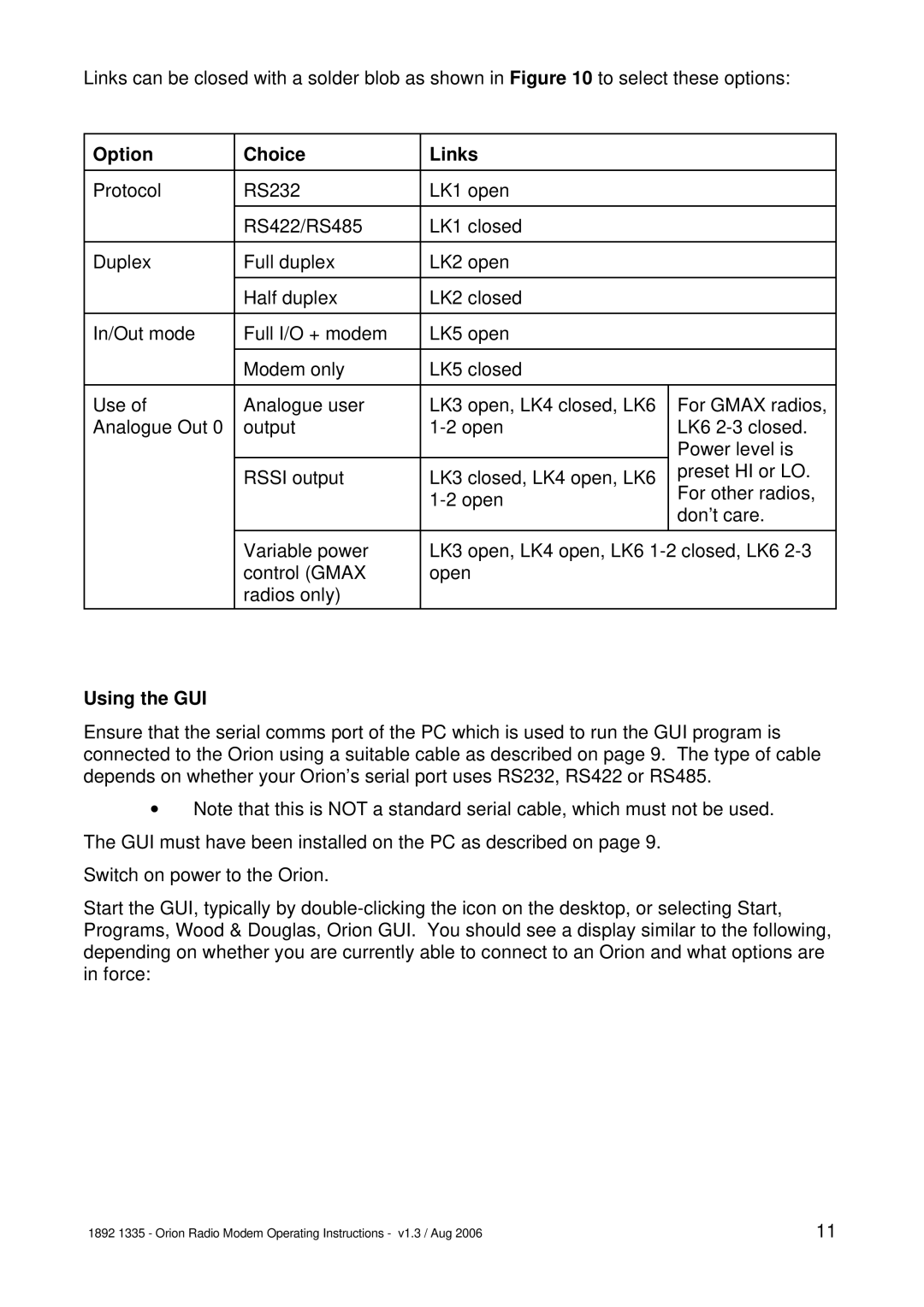
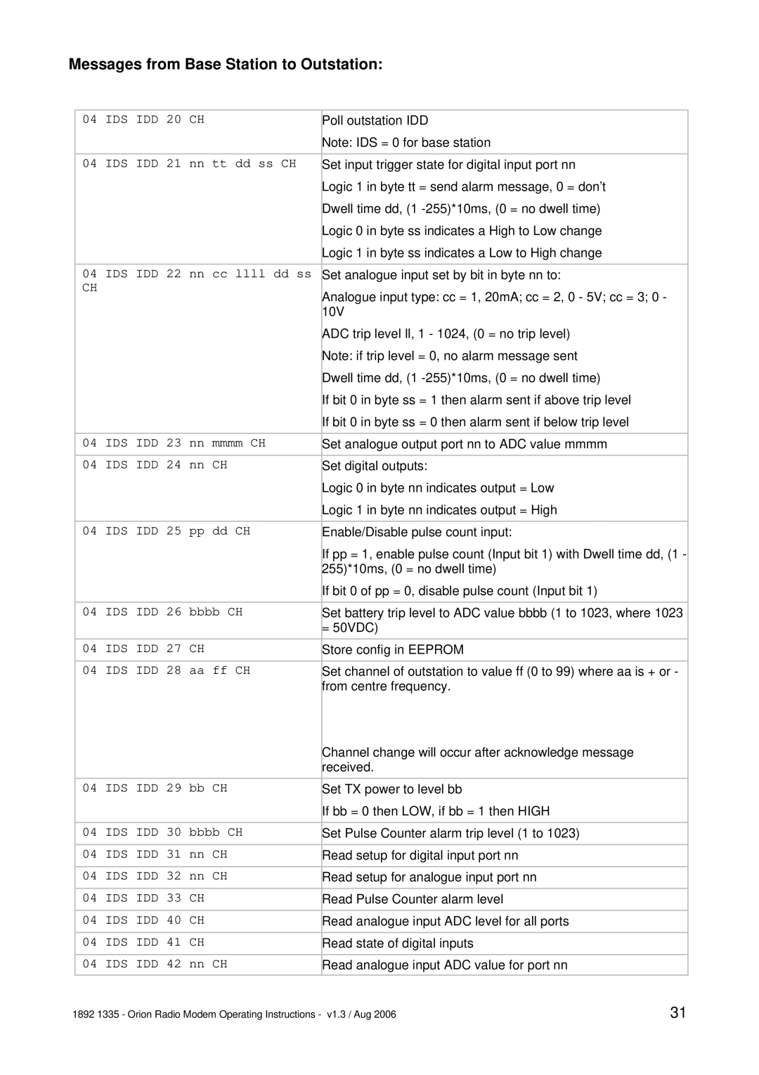
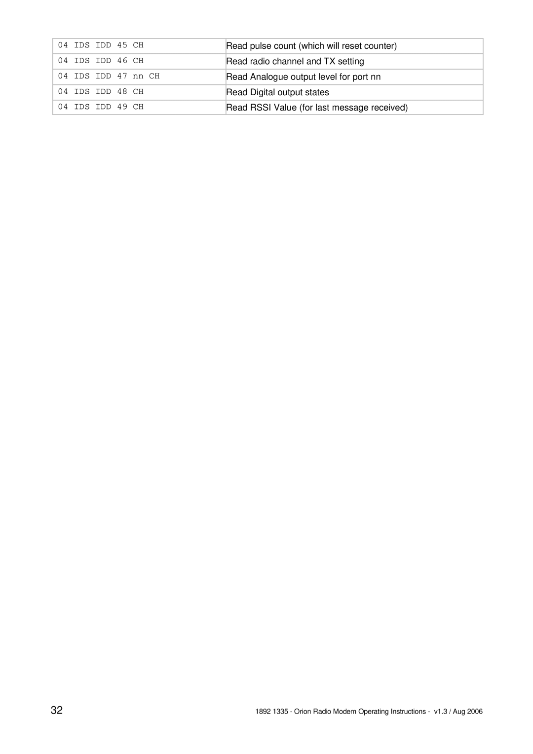
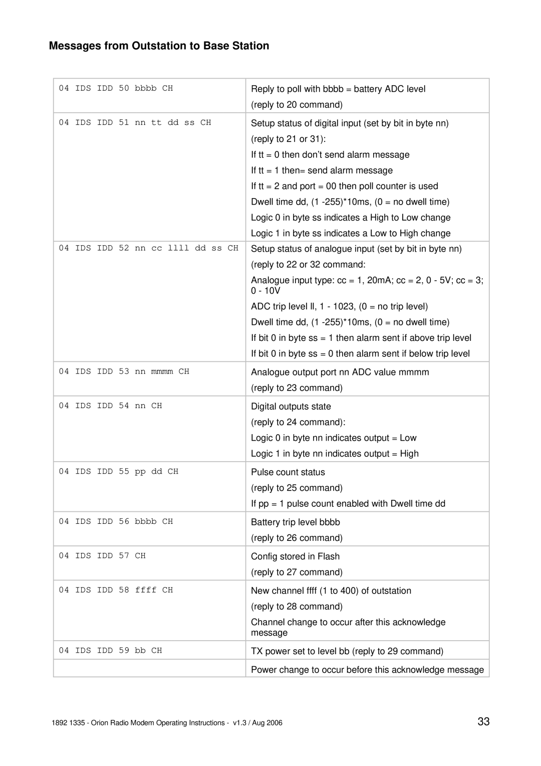
Contents Orion Radio Modem Orion Radio Modem with I/O Operating InstructionsOverview Shows the Orion in block diagram formPage Options When Ordering Physical InstallationDimensions of Orion PCB mm RJ45 Port Pin No Digital Digital Out Analogue Analogue Out ConnectionsTXB Pin No RS232 RS422 RS485Graphical User Interface GUI Hardware Link Settings Setting UP AN OrionOption Choice Links Using the GUIPage COM Ports and General Status Modem Modes TMR TNT TMX TNX TOM TOS TRR TSR TURTOR TOT TOX TOT Modem Parameter ConfigurationPage This space reserved for additional material Analogue In Set-up Telemetry Option ConfigurationAlarms This space reserved for additional material LED Indications OperationWait+++waitenter Appendix a AT Command CodesATS154= Command SyntaxEnd Command Mode Letter 0, not zero Ending Command Mode ATOCommands Description Values Start Command Mode Wait period set by ATS154=AT&Y8 AT&F=AT&F? AT&WATPT= ATPF?ATPRT= ATPRT?ATS168= ATS166?ATS167= ATS167?ATT? Introduction Appendix B OVER-AIR Command CodesIDS IDD 20 CH Messages from Base Station to OutstationIDS IDD 45 CH IDS IDD 51 nn tt dd ss CH Messages from Outstation to Base StationIDS IDD 65 nn cccc CH Page Appendix C ATT? Parameter String Structure