vFLASH FACTORY SETTINGS CORRUPT! (Error code 4)
When the modem was first programmed at the factory, a backup factory settings table was written in the FLASH memory. This is used if it is necessary to invoke the Reprogram with Factory Settings command. You can write your own custom settings into this backup table if you wish, using menu item Link, Factory settings, Write, which is password protected.
If this is corrupt, please consult Wood & Douglas technical support for assistance.
vPLL NOT IN LOCK! (Error code 16)
If the radio PLL does not lock, the radio module might be damaged. Turn off power to the unit, and power it up again. If this does not clear the error, please consult Wood & Douglas technical support for assistance.
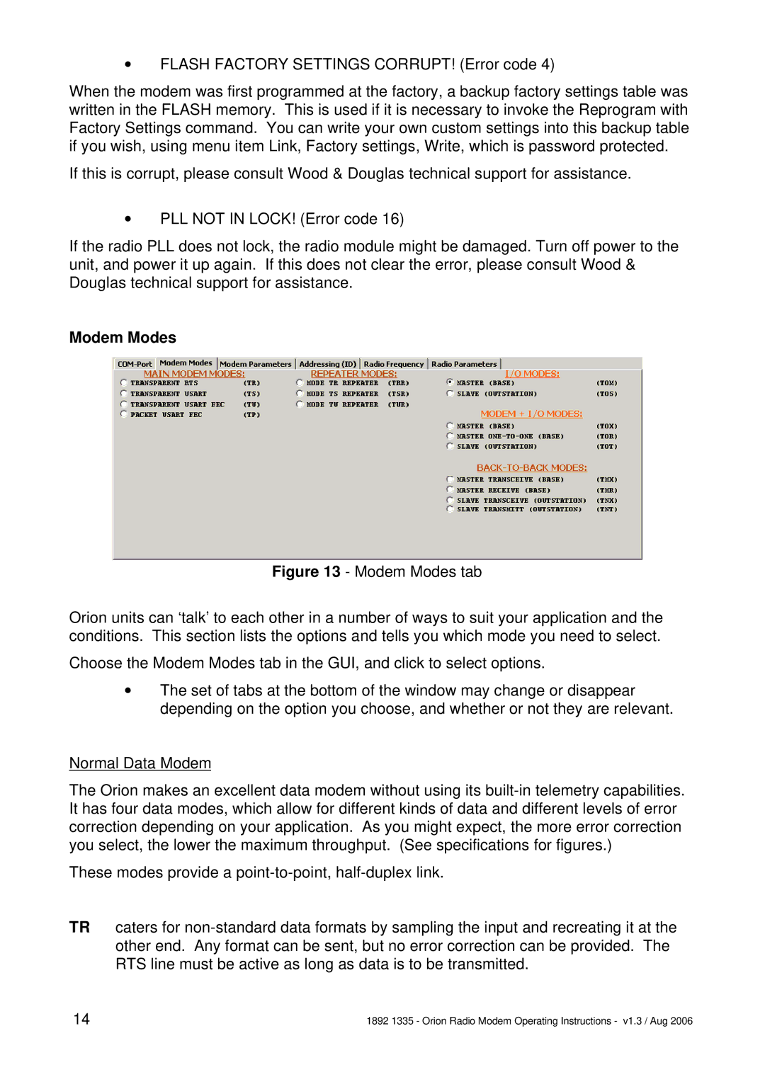
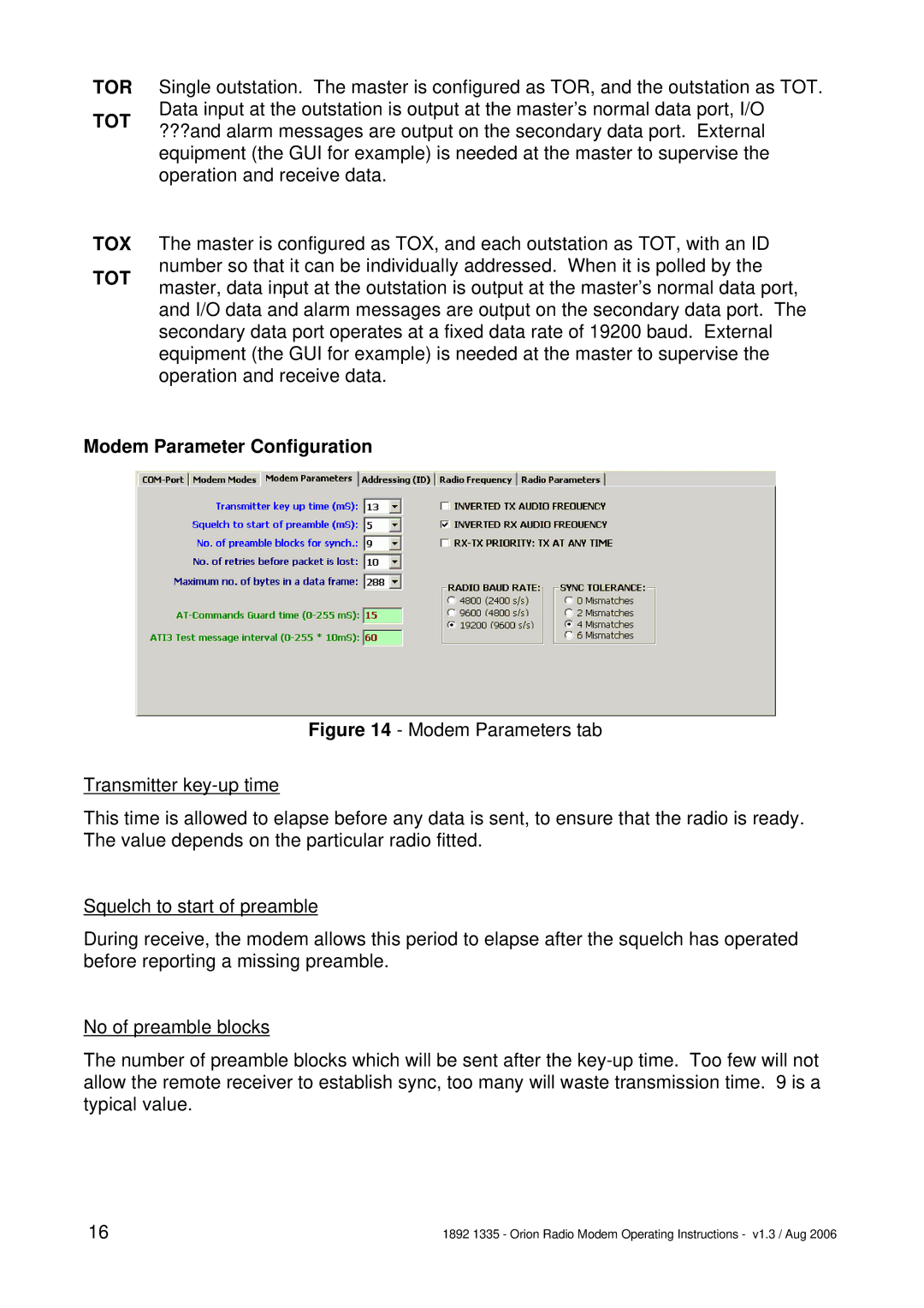
Modem Modes
Figure 13 - Modem Modes tab
Orion units can ‘talk’ to each other in a number of ways to suit your application and the conditions. This section lists the options and tells you which mode you need to select.
Choose the Modem Modes tab in the GUI, and click to select options.
vThe set of tabs at the bottom of the window may change or disappear depending on the option you choose, and whether or not they are relevant.
Normal Data Modem
The Orion makes an excellent data modem without using its built-in telemetry capabilities. It has four data modes, which allow for different kinds of data and different levels of error correction depending on your application. As you might expect, the more error correction you select, the lower the maximum throughput. (See specifications for figures.)
These modes provide a point-to-point, half-duplex link.
TR caters for non-standard data formats by sampling the input and recreating it at the other end. Any format can be sent, but no error correction can be provided. The RTS line must be active as long as data is to be transmitted.
14 | 1892 1335 - Orion Radio Modem Operating Instructions - v1.3 / Aug 2006 |
