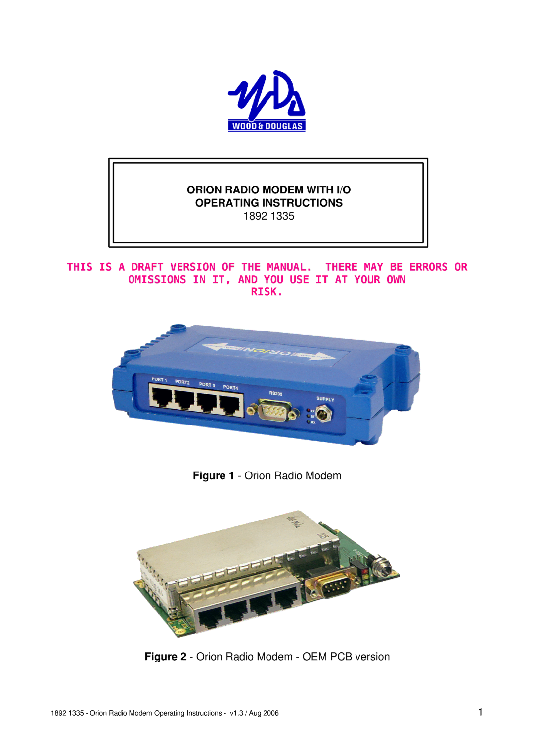
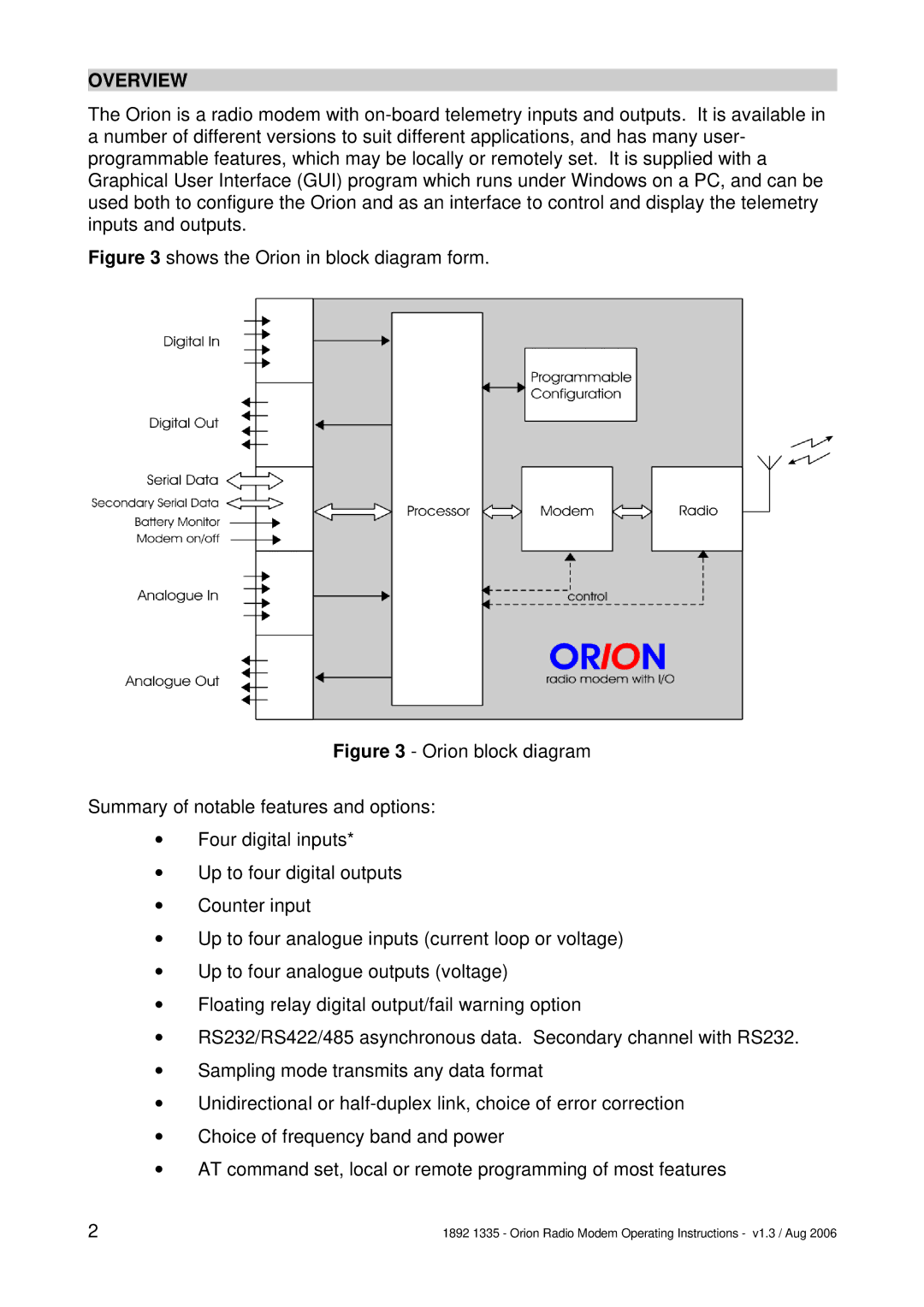
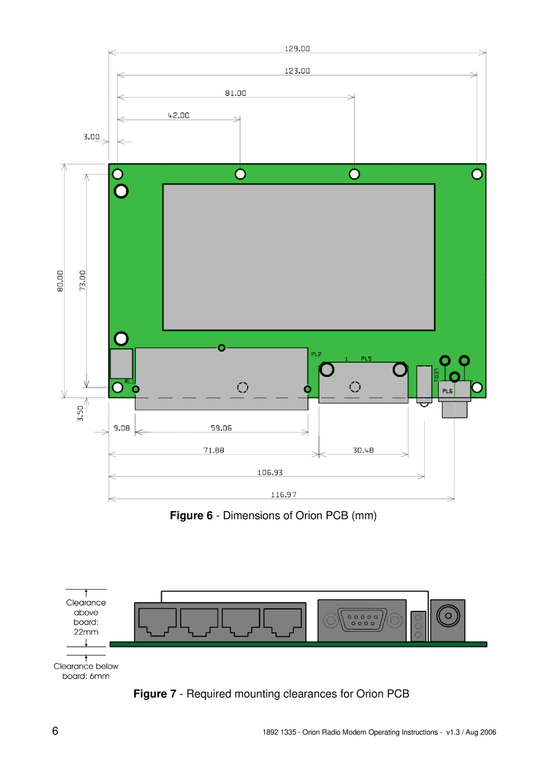
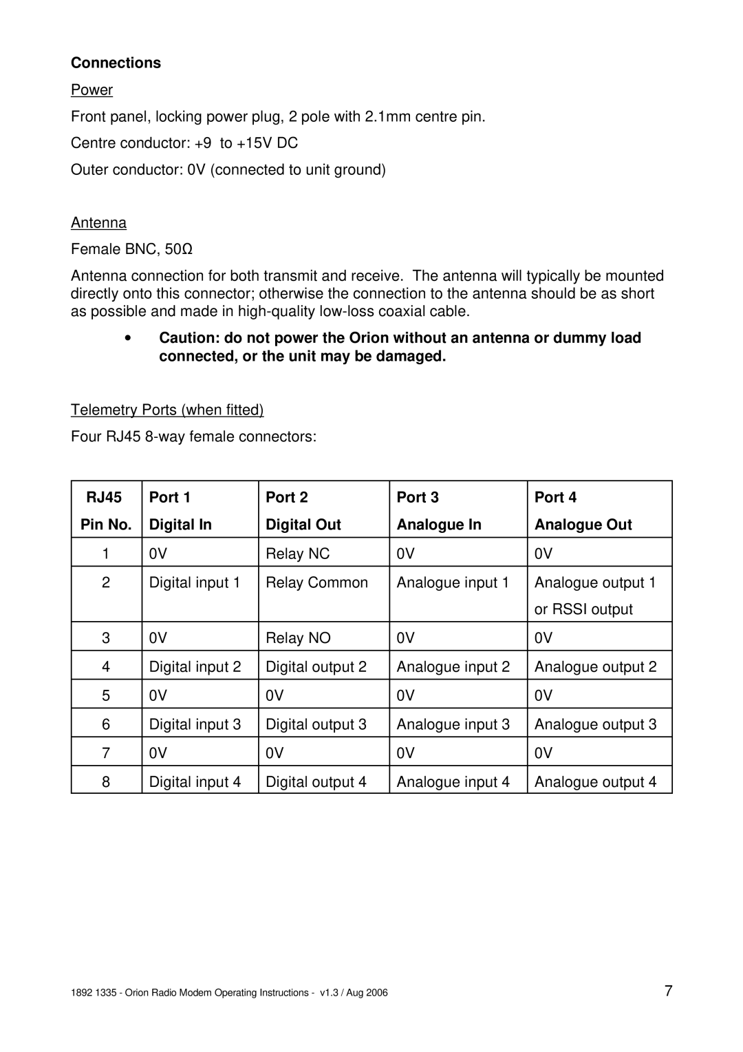
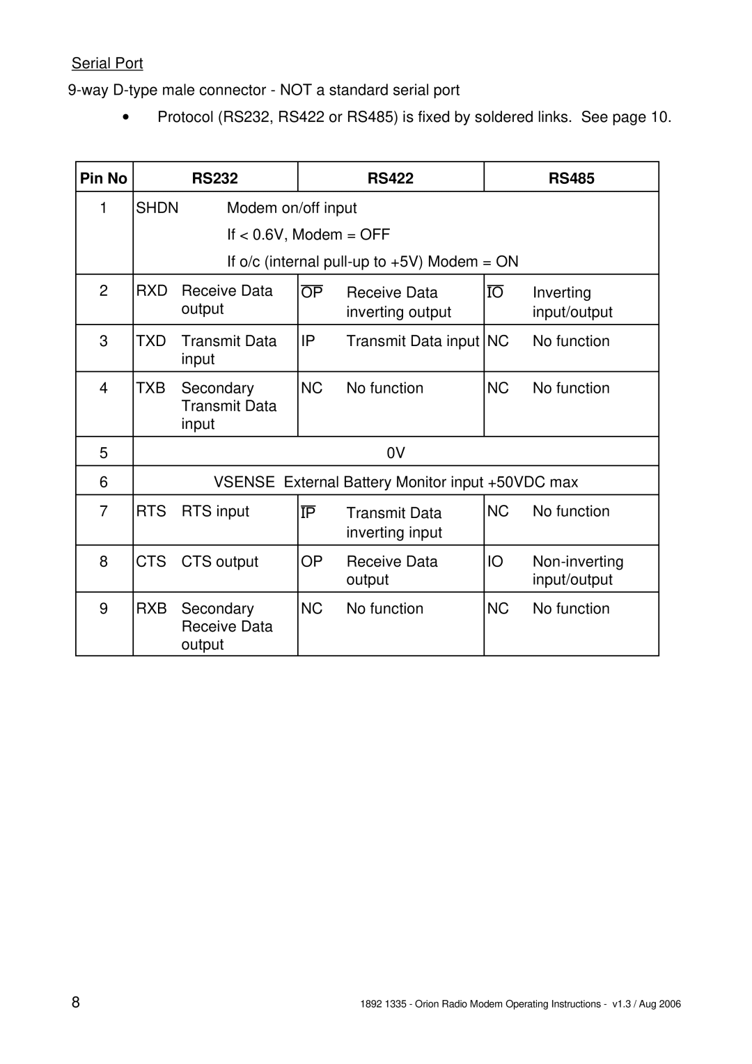
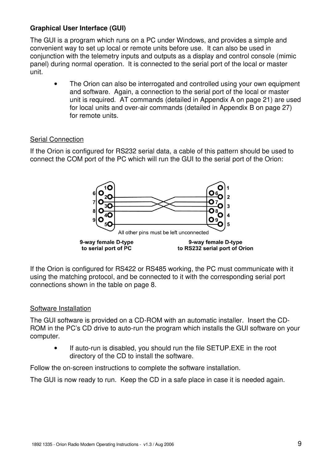
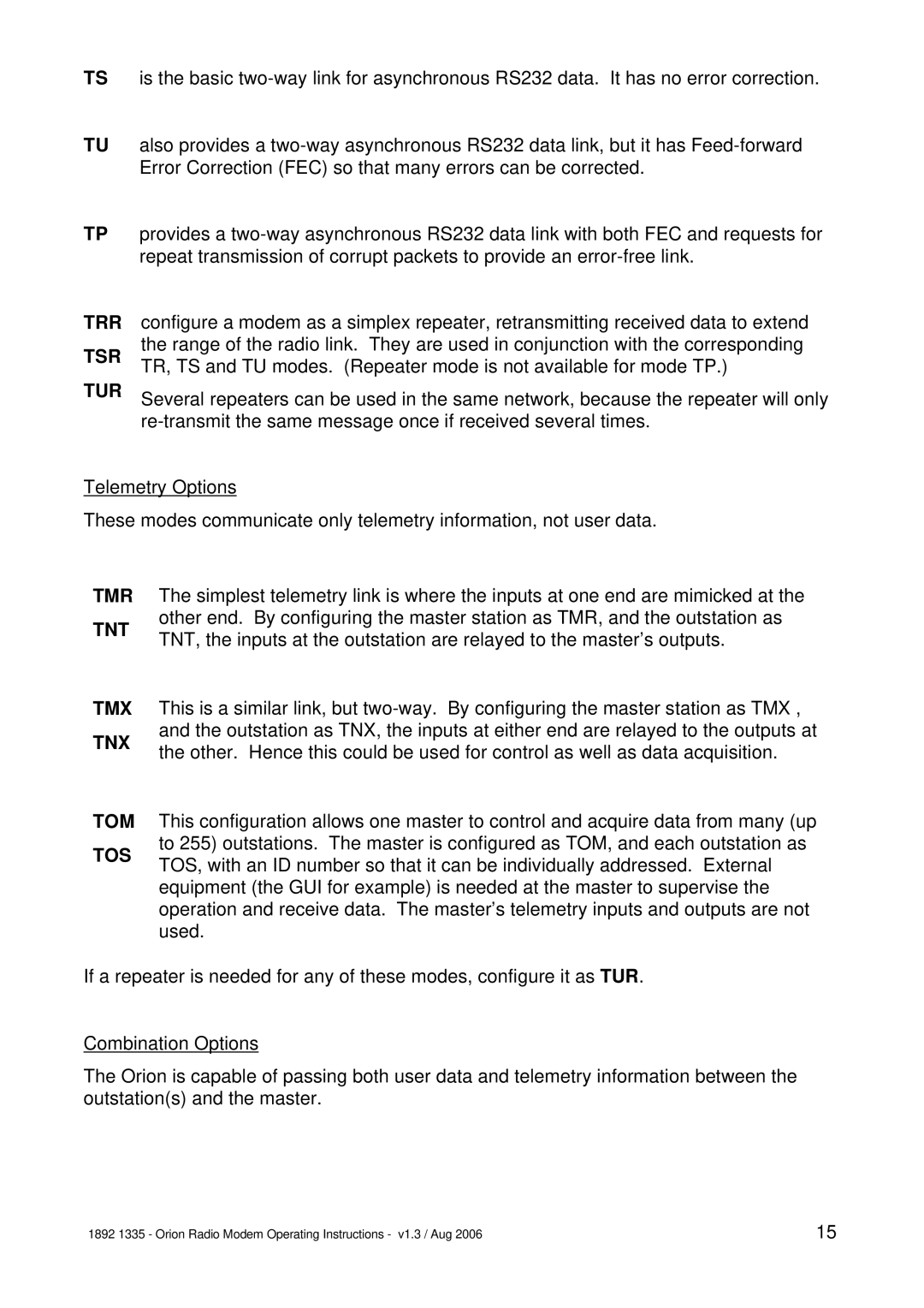
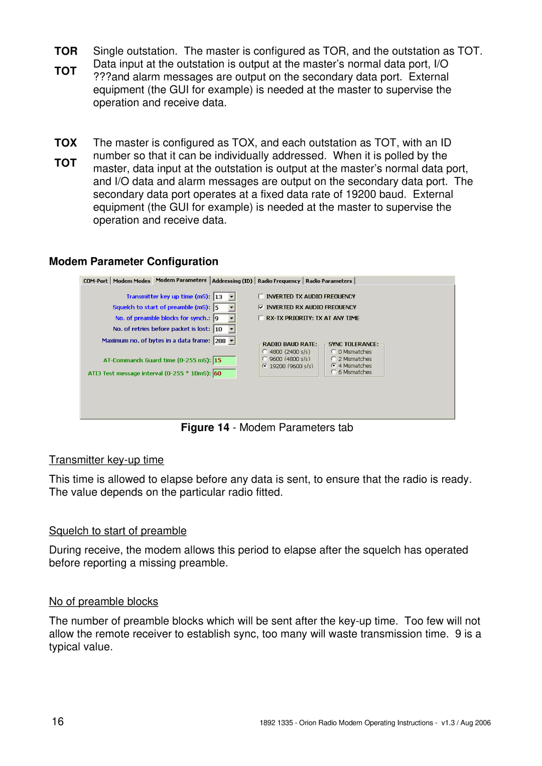
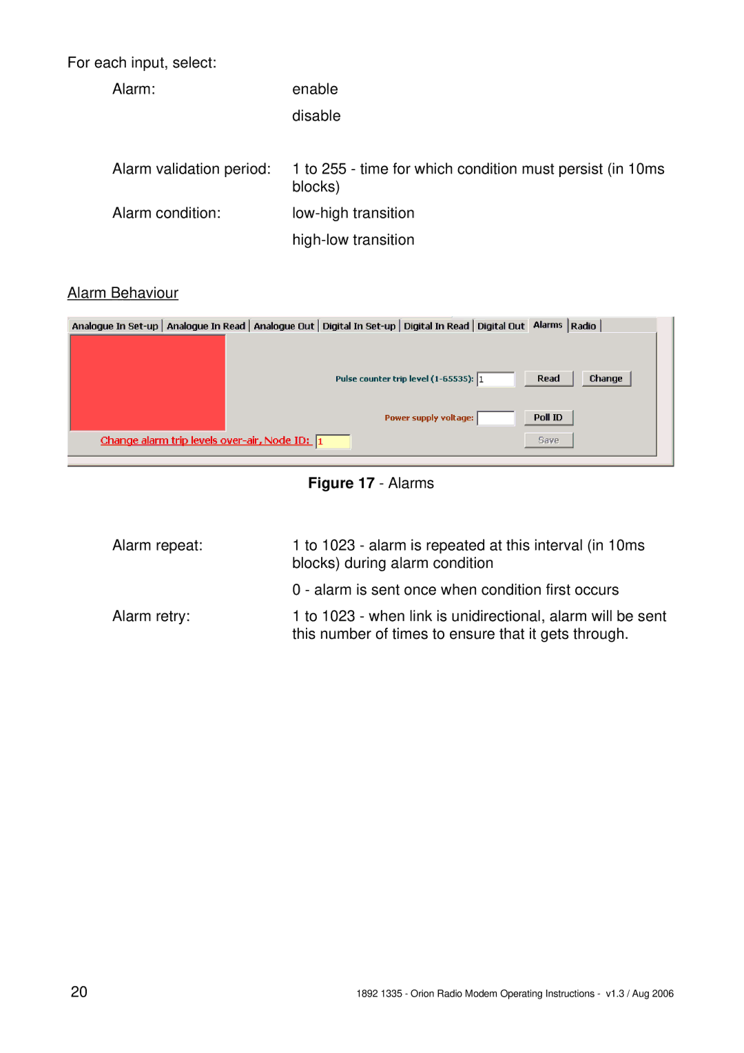
Orion Car Audio 1892 1335 manual Overview, Shows the Orion in block diagram form

Page 2

OVERVIEW

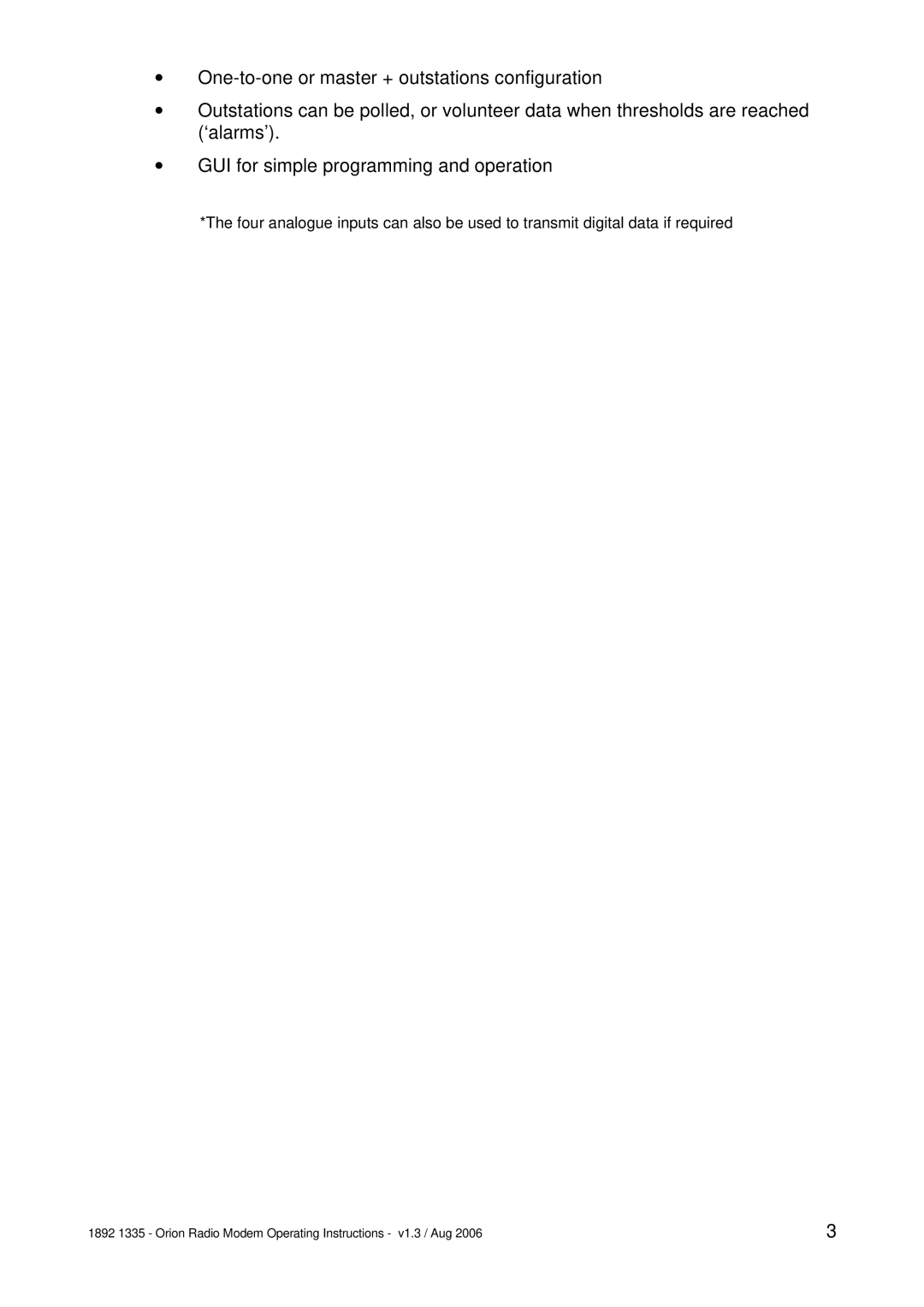
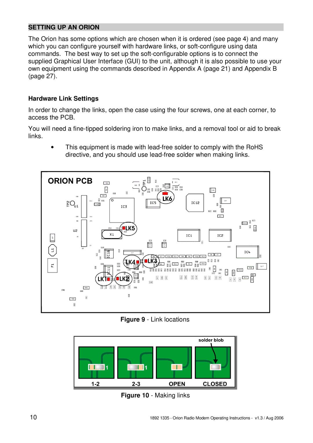
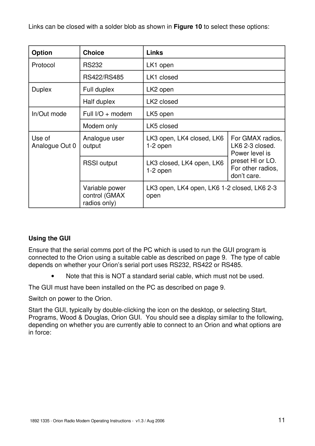
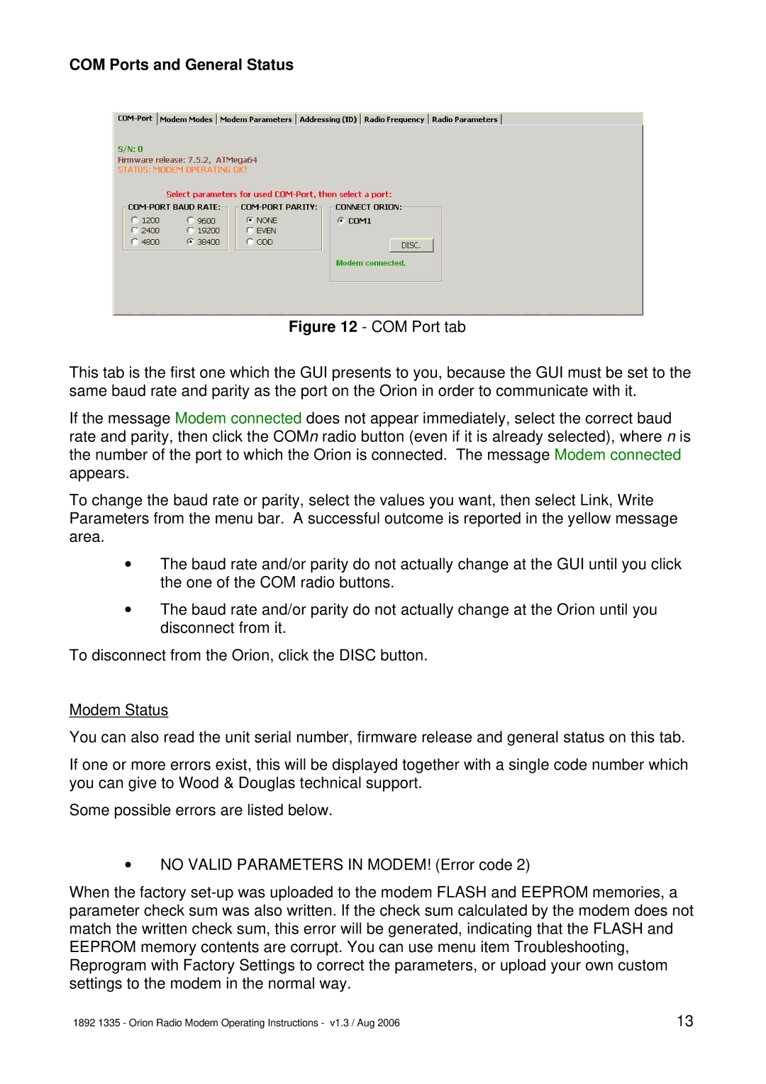
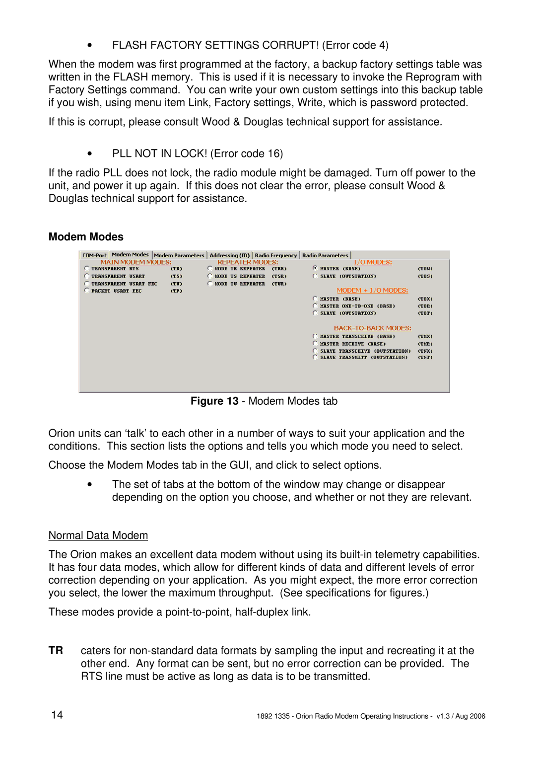
The Orion is a radio modem with on-board telemetry inputs and outputs. It is available in a number of different versions to suit different applications, and has many user- programmable features, which may be locally or remotely set. It is supplied with a Graphical User Interface (GUI) program which runs under Windows on a PC, and can be used both to configure the Orion and as an interface to control and display the telemetry inputs and outputs.

Figure 3 shows the Orion in block diagram form.

Figure 3 - Orion block diagram

Summary of notable features and options:

vFour digital inputs*

vUp to four digital outputs

vCounter input

vUp to four analogue inputs (current loop or voltage)

vUp to four analogue outputs (voltage)

vFloating relay digital output/fail warning option

vRS232/RS422/485 asynchronous data. Secondary channel with RS232.

vSampling mode transmits any data format

vUnidirectional or half-duplex link, choice of error correction

vChoice of frequency band and power

vAT command set, local or remote programming of most features

2

1892 1335 - Orion Radio Modem Operating Instructions - v1.3 / Aug 2006

Image 2
Contents Orion Radio Modem with I/O Operating Instructions Orion Radio ModemShows the Orion in block diagram form OverviewPage Options When Ordering Installation PhysicalDimensions of Orion PCB mm Connections RJ45 Port Pin No Digital Digital Out Analogue Analogue OutPin No RS232 RS422 RS485 TXBGraphical User Interface GUI Setting UP AN Orion Hardware Link SettingsUsing the GUI Option Choice LinksPage COM Ports and General Status Modem Modes TRR TSR TUR TMR TNT TMX TNX TOM TOSModem Parameter Configuration TOR TOT TOX TOTPage This space reserved for additional material Telemetry Option Configuration Analogue In Set-upAlarms This space reserved for additional material Operation LED IndicationsAppendix a AT Command Codes Wait+++waitenterCommand Syntax ATS154=Start Command Mode Wait period set by ATS154= Ending Command Mode ATOCommands Description Values End Command Mode Letter 0, not zeroAT&W AT&F=AT&F? AT&Y8ATPRT? ATPF?ATPRT= ATPT=ATS167? ATS166?ATS167= ATS168=ATT? Appendix B OVER-AIR Command Codes IntroductionMessages from Base Station to Outstation IDS IDD 20 CHIDS IDD 45 CH Messages from Outstation to Base Station IDS IDD 51 nn tt dd ss CHIDS IDD 65 nn cccc CH Page Appendix C ATT? Parameter String Structure