Milan Technology MIL-S1000 user manual

Page 33

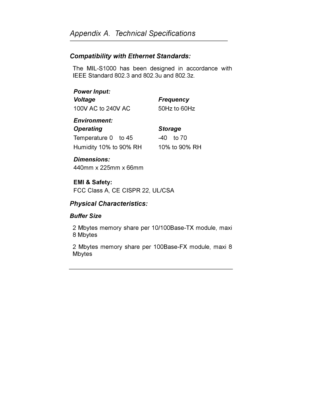
The MIL-S1000 switch is equipped with a universal switching power supply that accepts AC input voltages from 100 to 240VAC and 50 to 60 Hz.

To supply power to your switch:

1.Plug the connector of the power cord into the power port on the rear panel of your switch.

2.Plug the other end of the power cord into an AC wall outlet.

3.Set the power switch to ON and verify that the Power LED is lit. If it is not, check the following:

"The power switch is in the ON position.

"The power cord is properly connected to the wall outlet and to the power connection on the switch.

"The wall outlet is functional.

Note: Network cable segments can be connected or disconnected from the switch while the power is on, without interrupting the operation of the switch.
Image 33
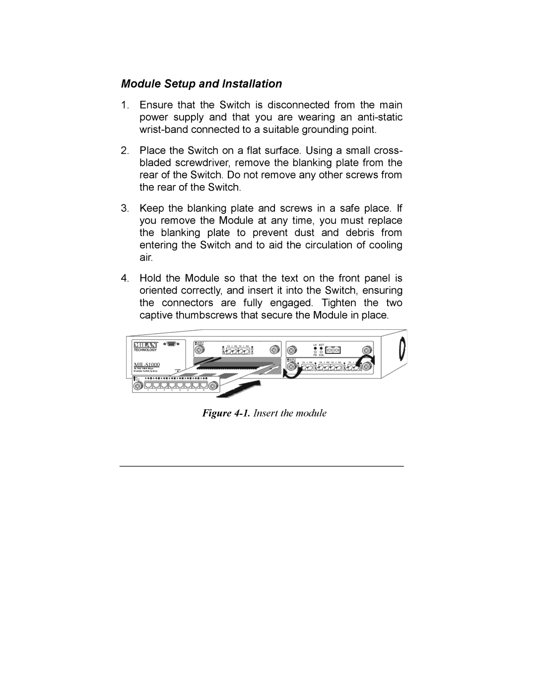
Contents MIL-S1000  Copyright Planning your Network Table of Contents IntroductionModule Install and Removed InstallationIntroduction Package Contents MIL-S1000 Front and Rear Panels Device Description, Features and CapabilitiesRed Full Duplex/Col indicators Page Ports 10/100Base-TX Module Ports 10/100Base-Tx Module FeaturesDip switch location and mode settings DIP Switch with Link Mode8 Ports 10/100Base-TX Module DIP switch functions 2 port 100Base-FX Module Front View Ports 100Base-FX Fiber ModulePorts 100Base-FX Fiber Module Features Page 4 port 100Base-TX/FX Front View Ports 100Base-FX Fiber Module Feature Location and setting duplex modePage 1000Base-SX/LX Fiber Module 1000Base-SX/LX Fiber Module FeaturesEnable N-way Full Duplex 10Base-T Ethernet Network Guidelines Planning your Network100BASE-FX Network Guidelines 100Base-TX Ethernet Network GuidelinesNetwork Planning 1000BASE-SX and LX Network Guideline10Base-T Networks Expanded NetworksExpanding your 100Base-TX network Class 100Base-TX NetworksCollapsed Backbone Link Fileserver Link 100Base SolutionFileserver Link Multiport Bridge with High-Bandwidth Backbone 1000Base SolutionUsed as a Multiport Bridge Installation Rack Installation Supplying PowerPage Connecting the Switch Handling the Modules Module Installation and RemovalInsert the module Module Setup and InstallationInstalling the Modules Installing 10/100Base-TX ModulesInstalling 100Base-FX Modules Removing the Modules Installing 1000Base-SX/LX ModulesCompatibility with Ethernet Standards Physical CharacteristicsLED Indicators Switching ArchitectureAddress Table Forwarding RateAppendix B. Pin Assignments Switch Adapter Hub