GE Series 90-70 manual Data Sent by the Master, Data Returned by Slaves

Page 14

1

Data Sent by the Master

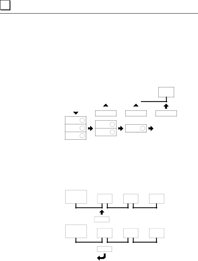
The master sends output data for all slave devices together. If a Series 90±70 PLC is the master on an I/O Link, it simply places the data to be sent into the %Q output references assigned to the I/O Link Interface Module.

Slaves receive the data in order of their positions on the link. Each slave in turn reads out its configured amount of data, and passes the remainder on to the next slave. To a slave, data received from the master is input data. If a Series 90±70 PLC is a slave, it obtains the data received from the master by reading the %I input references assigned to the I/O Link Interface Module.

MASTER


SLAVE


SLAVE


1


2


INPUTS

INPUTS

OUTPUTS

1


OUTPUTS

2

OUTPUTS

2

OUTPUTS 3


OUTPUTS

3

OUTPUTS

3


a45009

SLAVE

3

INPUTS

Data Returned by Slaves

The master continuously reads the output data from each slave. If a Series 90±70 PLC is a slave, it provides this data by placing it into the %Q references configured for the I/O Link Interface Module. If a Series 90±70 PLC is the master, it reads the data from the %I references assigned to the I/O Link Interface Module.

MASTER

SLAVE

1

SLAVE

2

a45004

SLAVE

3

INPUTS

MASTER

SLAVE

1

SLAVE

2

SLAVE

3

OUTPUTS

The master identifies each set of data it receives with respect to the slave's position on the link. To the master, data received from slaves is input data.

10

Series 90t-70 I/O Link Interface Module User's Manual ± February 1993

GFK-0644A

Image 14
Contents GE Fanuc Automation GFL±002 We Welcome Your Comments and Suggestions Content of this ManualRelated Publications Contents Chapter Introduction System OverviewMaster or Slave Operation Application Software Module Description LEDsSerial Ports Module SpecificationsReset Pushbutton Cable Types for the I/O Link CatalogNumberCable Lengths on the I/O Link Optical Adapter Operation of the I/O Link Input and Output DataData Sent by the Master Data Returned by SlavesInputs and Outputs Hold Last State Faults on the I/O Link Diagnostics Link ControlComplete the program logic for the I/O Link Module Install the module and complete the I/O LinkGetting Started Chapter Installation Installing the I/O Link Interface Module in the RackRemoving the I/O Link Interface Module from the Rack LED Name LED Status IndicationLink Module Used as a Master Connecting the I/O Link Interface Module to Other DevicesPorts on the I/O Link Module Order of the Devices on the Link Serial Port Pin AssignmentsLink Module Used as a Slave Cable Diagram, No Optical Adapter Cable Connections Optical Adapter InstallationCable Diagram, Electrical Cable to Optical Adapter Chapter Logicmaster 90-70 Configuration Configuration StepsGFK-0644A Chapter Programming Guide OverviewSelecting a Program Block Adding the Program Block Logic to an Application ProgramExample Call Instruction Using Multiple Calls to the Program BlockCalling the Program Block Program %P References for the I/O Link Program Blocks 3rdModule 4thModuleUsing Nicknames for the %P References Global %G References for the I/O Link Program BlocksConfiguring I/O Links Configuration Logic, ExampleConfiguration Guidelines Specify the Number of I/O Link ModulesControlling the I/O Link Module Set Master or Slave Mode bitReset or Stop bit Start/Restart bitDisable or Enable the Input Update bit Disable or Enable the Output Update bitMonitor Communications Status bit Monitoring Link OperationMonitor the Module bit Monitor for an Invalid Configuration or Link Fault bit Monitor for Link Failure bitError Codes Troubleshooting Error Description RecommendedAction CodeConfiguration Error Codes Index GFK-0644A Index