Epson R1400 installation instructions 43mm

Page 17

43mm

Fig.45


Fig.46


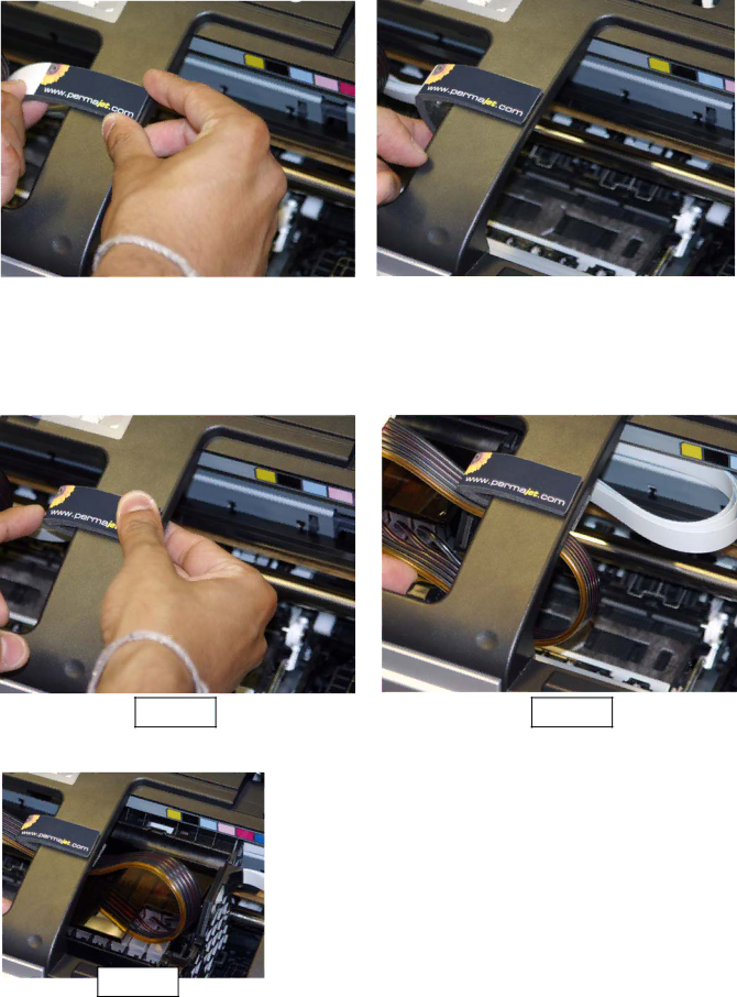
Position the Foam Strip in its correct location as indicated in Fig.45, You MUST align the Foam Strip flush to the edge ensuring that you lightly tack

the right hand side onto the casing.

Fig.47

Now ensure that you lightly tack down the bottom halve of the Foam Strip.

Fig.49

When you have placed the right hand side of the Foam Strip, very carefully bend it back to the white point as illustrated in Fig.46.

Fig.48

Please move the head manually across ensuring

that it travels in perfect alignment under the Foam Strip. If you are happy with the position and movement press firmly on the top and bottom halves of the Foam Strip so that it adheres to each side of the casing. Please also see Fig.49 to the left.

17

Image 17
Contents Epson R1400 Eco-Flo Shown What you will need to Install the Eco-Flo R1400What is included in your Eco-Flo R1400 Kit Check List for Components Check Printer Condition Disconnecting Power From the PrinterRemoving the Injector Lid Installation of Your ECO-FLO KITTube Preparation Moving the Printer HeadBottle Preparation Showing Tubes stripped back Positioning the Ink Bottles in The Tray Preparation of The Clamps & InksAssembling the Tubing to the Bottle Caps Page Contacts Installing the Chip Block UnitInstalling the Chip Support Bars Fixing the Special Printer Lid Install InjectorsUnlocking the Tube Clamps 47mm Install Final Tube Clip Installing the Foam Strip 43mm HOW the Special Permachip Works Testing the SystemRemoving the Injectors On the Compact Disc FAQ»S & Caring For Your Eco-Flo √ Read Carefully