JAI M7+ CL, CV-M4+, CV-M7+, M4+ CL operation manual Locations and Functions

Page 4

CV-M4+/M4+CL, CV-M7+/M7+CL

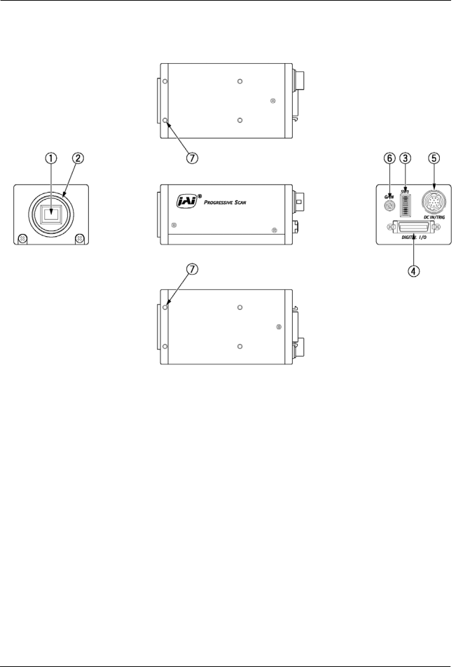
4. Locations and Functions

1.CCD sensor

2.Lens mount (C-mount)

3.Rear panel with SW1

4.Digital output connector

5.DC in/Trigger in/RS-232C connector

6.Gain potentiometer

7.Mounting holes M3

Fig. 1. Locations

- 3 -

Image 4
Contents CV-M4+/M4+CL CV-M7+/M7+CL CV-M4+/M4+CL, CV-M7+/M7+CL General Main FeaturesStandard Composition Locations and Functions LocationsDigital Output Connector for EIA-644 Lvds Pin Multi-connector DC-IN/RS232CPin Assignment Video signal, LEN, FEN Digital Output Connector for Camera LinkDval and EEN Input and Output Circuits Video outputTrigger input Multi Shutter input Composite Sync outputCamera Link interface MUXFunctions and Operations CV-M4+Block DiagramBasic functions Binning Color versions CV-M7+and CV-M7+CL Color coding from a Primary RGB CCD Bayer filterOutput of Timing Signals Restart Continuous Trigger mode. RCTContinuous Operation Non triggered Polarity and other functionsVertical timing details, full frame Vertical timing details with 1/2 partial scanning External Trigger Modes Accumulation latency time for H a-synchronous triggerEdge Pre-select Mode Important notes on using this modeEdge Pre-select, smearless Pulse Width Control Mode Pulse WidthFrame-delay read out Mode Frame DelayFrame-delay read out Mode with multiple exposure Multiple exposure, normal and smearlessOther Functions Gain and set-upConfiguring the Camera Mode setting SW1 on rearMode setting SW301 inside Internal Switch and Jumper SettingsRS-232C control CV-M4+command list Timing and shutter related commandsCamera Control Tool for CV-M4+ Specifications External Appearance and DimensionsSpectral sensitivity Specification table SpecificationsTypical CCD Characteristics PrecautionsAppendix Camera Link Test points Camera Link test pointsUsers Mode Settings Users Modifications Users Record