| ~ | i/e"LO~/HEIGHTNUT | |
,, | // |
| |
" |
|
|
|
.... |
|
|
|
II |
| ,' | ', |
2 IN, SQ, END CAP~
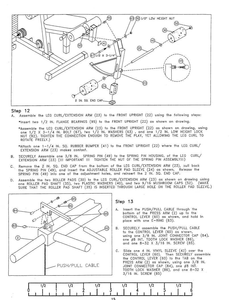
Step 12
A.Assemble the LEG CURL/EXTENSIONARM (25) to the FRONTUPRIGHT (22) using the follow;ng steps: ~lnsert two 1/2 IN. FLANGE BEARINGS(95) to the FRONTUPRIGHT(22) es shown on drewing.
~Assemble the LEG CURL/EXTENSIONARM (25) to the FRONTUPRIGHT (22) r~s shown on drawing, using
one 1/2
~Aff(~ch one
B. SECURELYAssemble | one | .5/8 IN. SPRING PIN (49) to the SPRING PiN HOUSING, of the LEG CURL/ |
EXTENSIONARM (25) | (!!! | IMPORTANT!!! TIGHTEN THE NUT OF THE SPRING PIN ASSEMBLY!!!) |
C.. Remove the ~ IN. SQ. END CAP from the bottom of the LEG CURL/EXTENSIONARN (25), 3ull back
:the SPRING PIN (49), and Insert the ADJUSTABLEROLLER PAD SLEEVE (24) es shown. Release SPRINGPIN (49) into one of the adiusfment holes, and reinsert the 2 IN. SQ. END CAP.
D.Assemble the two ROLLER PADS (50) to the LEG CURL/EXTENSION ARM (2.5) as shown on drawing Using one ROLLER PAD SHAFT (55), two PLASTIC WASHERS(40), Grid two 9/16 MUSHROOMCAPS (52).
SURE THAT THE ROLLER PAD SHAFT (55) IS INSERTED THROUGHLARGE HOLE ON THE ROLLER PAD SLEEVE.)
Step 13
PUSH/PULL CABLE
Inser! the PUSH/PULL CABLE through the bottom of the PRESSARM (2) up to the CONTROLLEVER (60) as shown, cmd hold piece with one
SECURELY assemble the PUSH/PULL CABLE to the CONTROLLEVER (60) os shown,
using one 5/8 IN. JOINT CONNECTORCAP (84), one #8 INT. TOOTHLOCI< WASHER(86),
end one
Slide one 4 IN. VINYL SLEEVE(42_) over the CONTROLLEVER (60). Then SECURELYassemble
the CONTROLLEVER (60) fo the TAB on the PRESS ARM (2) as shown, using one 5/8 IN.
JOINT CONNECTORCAP (84), one #8 INT. TOOTH LOCK WASHER(86), end one
I | 1/2 | I | 1/2 | I |
4 |
| 5 | I I_1 | 6 |
I ! | i I I | I | ||