Nordyne RC 92+, RL 90+ Return Air, Venting and Combustion AIR Requirements

Page 13

Return Air

The return air ductwork may be connected to any or all of the following: left side return, right side return, or bottom return. Tables 1 and 2 show the airflow data for each furnace model. Where maximum airflow is 1800 CFM or more two openings must be used.

VENTING AND COMBUSTION AIR REQUIREMENTS

NORDYNE condensing furnaces may be installed with outdoor combustion air piped directly to the furnace, or without such special piping. Codes refer to the former as “direct vent” or “two pipe” installation. Installation with air taken from around the furnace is sometimes referred to as “one pipe” installation where only the vent (exhaust) pipe is provided.

Provisions must be made for adequate sup- ply of air for combustion and ventilation. For United States installations, the adequacy of air provisions can be determined by consulting the current version of the National Fuel Gas Code (ANSI Z223.1/NPFA-54). For Canadian installa- tions, requirements are specified in the National Standard of Canada (CAN/CGA B149.1 & .2). Consult local codes for special requirements.

An important consideration in selecting one or two pipe installation is the quality of the combus- tion air. Indoor air is sometimes contaminated with various household chemicals which can cause severe corrosion in the furnace combus- tion system.

NOTE: If the furnace is operated without ade- quate air for combustion and ventilation, it may not perform properly. Furnace components may be strained by high temperature and could fail .

!WARNING:

Furnace installation using methods other than those described in the fol- lowing sections must comply with the National Fuel Gas Code and all appli- cable local codes to provide sufficient combustion air for the furnace.

Concrete

Furnace

Floor


Sheet


Metal


Plenum

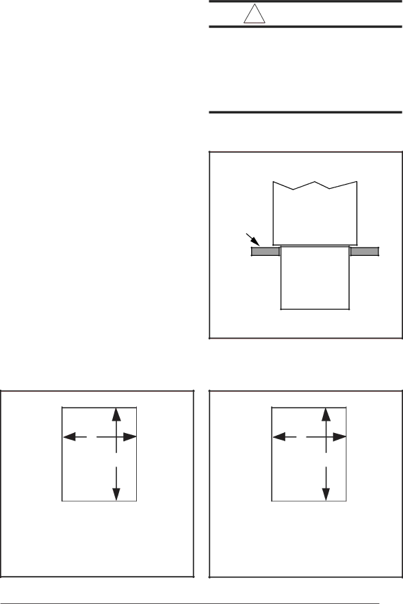
Figure 6. Furnace on a Concrete Slab

A

B

MODEL

A

B


*RL 040/060

13.25”

19.25”


*RL 080/100

18.75”

19.25”


*RL 120

21.50”

19.25”


Figure 5. Opening for Concrete Slab

A

B

MODEL

A

B


*RL 040/060

13.25”

19.63”


*RL 080/100

18.75”

19.63”


*RL 120

21.50”

19.63”

Figure 7. Opening in Wood Floor

13

Image 13
Contents What to do if YOU Smell GAS Installation InstructionsPage Table of Contents Furnace Specifications Downflow *RL Furnace G6RC Upflow Furnace Capacities -Furnace Airflow DataCapacities Installation Requirements Requirements and Codes Safety InformationImportant Note Minimum Clearances to Combustible Material Clearances to Combustible MaterialsDownflow Warning *RL Models Horizontal InstallationsLocation Vinyl Cap Grey Tubing Installation on a concrete slab *RL Supplyair Plenum InstallationInstallation on a combustible floor *RL Circulating AIR SupplyVenting and Combustion AIR Requirements Return AirFurnace on a Wood Floor Downflow Sub-Base DimensionsEquipment in a Confined Installation In An Unconfined Space Air Requirements For One-Pipe InstallationInstallation In a Confined Space Combustion Air QualityVenting Requirements Vent Pipe Material SolutionVent Pipe Length and Diameter Seal any unused openings in the vent- ing systemDownflow Furnaces Upflow FurnacesVent Table Pipe Routing and Support Vent Pipe InstallationLocation of Outdoor Terminations Horizontal VentingVertical Venting Page Vent Termination Clearances for Direct Vent Furnaces For appliances 100,00 Btuh 30 kW Vent Protection Vertical VentingVent Freezing Protection = 12 Above Roof or Snow Accumulation LevelUpflow Models Concentric Vent Termination Drainage of Condensate from FurnaceSide Wall Vent Kit Leak Check GAS Supply and PipingAbove Sea Level Manifold Pressure in WC for Natural Gas at Various AltitudesHigh Altitude Application ConversionNatural Gas High Altitude Conversion LP/Propane Gas Sea Level and High Altitude ConversionLine Voltage Wiring Electrical WiringLow Voltage Wiring Start-Up Procedure START-UP and AdjustmentsVerifying and Adjusting Firing Rate Firing rate = 1040 x 90 = 93,600 BtuhBlower Speed Tap Location Verifying and Adjusting Temperature RiseVerifying Burner Operation Verifying Operation of the Supply Air Limit SwitchDescription of Components Gas Flow RateMaintenance WD# For Upflow and Downflow Residential FurnacesDownflow Furnace Models Upflow Furnace ModelsSystem Operation Information Heating ModeSequence of Operation Fan Mode Cooling ModeFurnace Fails to Operate Twinning of Two FurnacesFuel Type INSTALLATION/PERFORMANCE Check List