Desa VDCFTNB Installation Items, Fireplace Clearances, Minimum Clearance to Combustible Materials

Page 10

INSTALLATION

Continued

INSTALLATION ITEMS

Before installing fireplace, make sure you have the items listed below.

external regulator (supplied by installer, for propane/LP units only)

piping (check local codes)

sealant (resistant to propane/LP gas)

equipment shutoff valve *

test gauge connection*

ground joint union

sediment trap

tee joint

pipe wrench

*A CSA design-certified equipment shutoff valve with 1/8" NPT tap is an acceptable alternative to test gauge connection. Purchase the optional CSA design-certified equipment shutoff valve from your dealer. See Accessories, page 40.

Note: If desired, purchase a four-sided perimeter trim kit for built-in installations. See Accessories, page 40.

FIREPLACE CLEARANCES

WARNING: Maintain the minimum clearances shown in Figure 6. If you can, provide greater clearances from floor, ceiling and joining wall.

If your fireplace is to be used with an optional mantel, the installation instructions included with your mantel shows an CSA approved method of attaching the fireplace/mantel system to a wall. IMPORTANT: Only use optional cabinet or corner mantels specified in this manual. Purchase the optional mantel from your dealer (see Acces- sories, page 40).

If your fireplace is to be recessed into the wall, see Built-In Fireplace Installation on page 11 to secure your fireplace into the wall.

CAUTION: If you install the fireplace in a home garage

fireplace pilot and burner must be at least 18 inches above floor.

locate fireplace where moving vehicle will not hit it.

For convenience and efficiency, install fireplace

where there is easy access for operation, inspec- tion and service

in coldest part of room

An optional blower kit is available from your dealer. See Accessories, page 40. If planning to use blower, follow instructions provided with blower for power source.

Minimum Clearances For Side

Combustible Material, Side Wall and

Ceiling

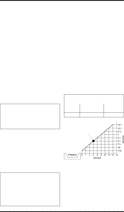
A.Clearances from the side of the fireplace cabinet to any combustible material and wall should follow diagram in Figure 6.

Example: The face of a mantel, bookshelf, etc. is made of combustible material and protrudes 3 1/2" from the wall. This combus- tible material must be 4" from the side of the fireplace opening (see Figure 6).

B.Clearances from the top of the fireplace opening to the ceiling should not be less than 36 inches.

C.For mantel clearances, see Figure 10 on page 12.

MINIMUM CLEARANCE TO COMBUSTIBLE MATERIALS

Top

Left and

Bottom


Right Sides

and Rear

36"

6"

0"


Example


*

*Minimum 16 inches from Side Wall

Figure 6 - Minimum Clearance for

Combustible to Wall

10

www.desatech.com

116526-01A

Image 10
Contents Shown with Optional Cabinet Mantel/Hearth Base Accessory What to do if YOU Smell GASTable of Contents Safety Information Safety Information Local Codes Product FeaturesProduct Identification UnpackingTools Required Phillips screwdriver Hood AssemblySheet Metal Screws Hood Louver Firebox Top Shoulder Screw Screen Providing Adequate Ventilation AIR for Combustion Ventilation Determining FRESH-AIR Flow for Fireplace Location Ventilation Air From Inside Building Ventilation AIRVentilation Air From Outdoors Installation Check GAS TypeMinimum Clearance to Combustible Materials Installation ItemsFireplace Clearances TopFront Width BUILT-IN Fireplace InstallationActual Framing Height DepthSide of Firebox Optional Mantel InstallationMantel Shelf Top Louver Bottom LouverInstalling Optional Blower Accessory GA3450TA Plate Remote Wire Blower Harness Bracket Lower Louver Door Installing Blower AccessorySwitch Power Cord SwitchExtension Cord For Built-In InstallationBlower Bracket Connecting to GAS Supply Installation Items Needed Connecting Equipment Shutoff Valve to Heater ControlChecking GAS Connections Equipment Open Shutoff Valve Closed Pressure Testing Fireplace Gas ConnectionsEquipment Shutoff Valve Propane/LP Supply Tank Gas Regulator or Gas Control Valve EquipmentReceiver Volt Terminal Battery Wires Battery Clip Optional Wireless HAND-HELD Remote Control AccessoriesInstalling Receiver Installing 9-Volt Battery in Hand-Held Remote Control UnitInstall the base onto the wall with the pro- vided screws Control Valve To Wall Thermostat or Switch Or SwitchFeed wires through rectangular slots Remove jumper wire from control valve see ,Operating Fireplace Installing LOG SET and ScreenFor Your Safety Read Before Lighting Lighting InstructionsThermostat Control Operation Manual Lighting ProcedureTo Turn OFF GAS To Appliance Shutting Off FireplaceAUTO/OFF/ON Switch REMOTE-READY Models For Your Safety Read Before LightingOperating Blower Pilot Ignitor Burner Electrode Piezo Flame Control Ignitor Adjustment Knob ButtonPilot Burner Ignitor Electrode Thermostat Series Model HRC200 Manual ModeOptional HAND-HELD Remote Operation ON/OFF Series Model HRC100Optional GWMS2 Wall Mounted Switch Optional GWMT1 Wall Mounted ThermostatCleaning Maintenance Inspecting BurnersAir Passageways LOG SETCabinet ExteriorTroubleshooting Observed Problem Possible Cause RemedyMote-Ready Models Only Burner orifice is clogged Clean burner see CleaningBurner orifice is clogged Models OnlySlight smoke or odor during When heated, vapors fromMote-Ready Models Only Power is low Nance,Gas leak. See Warning Thermostat Models SpecificationsRemote-Ready Models Illustrated Parts Breakdown Firebox Models VDCParts List Thermostat Models Vdcftpb and Vdcftnb Thermostat Models REMOTE-READY Models Vdcfrnb and Vdcfrpb KEY Part Numbers Vdcfrpb Vdcfrnb Description QTY Perimeter Trim KIT GA6095 AccessoriesEquipment Shutoff Valve GA5010 THERMOSTAT-CONTROLLED Blower KIT GA3450TInformation Video Receiver and HAND-HELD Remote Control KIT HRC100 SeriesFor all models. Creates the sound of a real burn- ing fire Technical Service Replacement PartsService Hints Parts Under Warranty116526-01A Keep this Warranty Warranty InformationLimited Warranty VENT-FREE Compact Classic Hearth