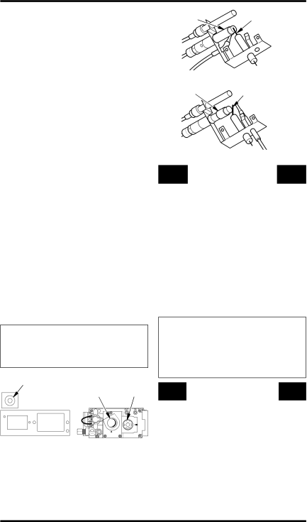
Desa VDCFTNB Piezo Flame Control Ignitor Adjustment Knob Button, Pilot Ignitor Burner Electrode

Page 24

OPERATING FIREPLACE

Continued

5.Press in and turn control knob counter-

clockwise to the PILOT position. Press in control knob for five (5) seconds (see Figure 38).

Note: You may be running this fireplace for the first time after hooking up to gas sup- ply. If so, the control knob may need to be pressed in for 30 seconds or more. This will allow air to bleed from the gas system.

6.With control knob pressed in, press and release ignitor button. This will light pilot. The pilot is attached to the front burner. If needed, keep pressing ignitor button until pilot lights.

Note: If pilot does not stay lit, contact a qualified service person or gas supplier for repairs. Until repairs are made, light pilot with match. To light pilot with match, see Manual Lighting Procedure.

7.Keep control knob pressed in for 30 seconds after lighting pilot. After 30 seconds, release control knob.

If control knob does not pop out when released, contact a qualified service person or gas supplier for repairs.

Note: If pilot goes out, repeat steps 4 through 8.

8.Slightly push in and turn control knob coun-

terclockwise to the ON position.

9.Set flame adjustment knob to any level between HI and LO.

CAUTION: Do not try to ad- just heating levels by using the equipment shutoff valve.

Piezo

Flame

Control

Ignitor

Adjustment

Knob

Button

Knob


Figure 38 - Control Knob and Ignitor

Button Location (Shown as Supplied

- No Control Options)

Pilot

Ignitor

Burner

Electrode


Figure 39 - Propane/LP Gas Pilot

Pilot Burner

Ignitor

Electrode


Figure 40 - Natural Gas Pilot

TO TURN OFF GAS

TO APPLIANCE

Shutting Off Fireplace

1.Turn control knob clockwise to the OFF position.

2.If Using Optional Hand-Held Remote: Set selector switch in the OFF position to prevent draining battery.

Shutting Off Burners Only (pilot stays lit) You may shut off the burners and keep the pilot lit by doing one of the following:

1.Turn control knob clockwise to the PILOT position.

2.If Using Optional Hand-Held Remote: Use remote control manual OFF button.

WARNING: Make sure re- mote sensor selector switch is in the OFF position when you are away from home for long periods of time.

MANUAL LIGHTING

PROCEDURE

1.Follow steps 1 through 5 under Lighting Instructions, starting on page 23.

2.Depress control knob and light pilot with match.

3.Keep control knob pressed in for 30 seconds after lighting pilot. After 30 seconds, release control knob. Now follow steps 8 and 9 under Lighting Instructions.

24

www.desatech.com

116526-01A

Image 24
Contents Shown with Optional Cabinet Mantel/Hearth Base Accessory What to do if YOU Smell GASTable of Contents Safety Information Safety Information Product Features Product IdentificationLocal Codes UnpackingHood Assembly Sheet Metal Screws Hood Louver Firebox TopTools Required Phillips screwdriver Shoulder Screw ScreenAIR for Combustion Ventilation Providing Adequate VentilationDetermining FRESH-AIR Flow for Fireplace Location Ventilation AIR Ventilation Air From Inside BuildingVentilation Air From Outdoors Installation Check GAS TypeInstallation Items Fireplace ClearancesMinimum Clearance to Combustible Materials TopBUILT-IN Fireplace Installation Actual Framing HeightFront Width DepthOptional Mantel Installation Mantel ShelfSide of Firebox Top Louver Bottom LouverInstalling Optional Blower Accessory GA3450TA Installing Blower Accessory Switch Power CordPlate Remote Wire Blower Harness Bracket Lower Louver Door SwitchFor Built-In Installation Extension CordBlower Bracket Connecting to GAS Supply Connecting Equipment Shutoff Valve to Heater Control Installation Items NeededChecking GAS Connections Pressure Testing Fireplace Gas Connections Equipment Shutoff Valve Propane/LP Supply TankEquipment Open Shutoff Valve Closed Gas Regulator or Gas Control Valve EquipmentOptional Wireless HAND-HELD Remote Control Accessories Installing ReceiverReceiver Volt Terminal Battery Wires Battery Clip Installing 9-Volt Battery in Hand-Held Remote Control UnitControl Valve To Wall Thermostat or Switch Or Switch Feed wires through rectangular slotsInstall the base onto the wall with the pro- vided screws Remove jumper wire from control valve see ,Installing LOG SET and Screen For Your Safety Read Before LightingOperating Fireplace Lighting InstructionsManual Lighting Procedure To Turn OFF GAS To ApplianceThermostat Control Operation Shutting Off FireplaceREMOTE-READY Models For Your Safety Read Before Lighting AUTO/OFF/ON SwitchOperating Blower Piezo Flame Control Ignitor Adjustment Knob Button Pilot Ignitor Burner ElectrodePilot Burner Ignitor Electrode Manual Mode Optional HAND-HELD Remote OperationThermostat Series Model HRC200 ON/OFF Series Model HRC100Optional GWMS2 Wall Mounted Switch Optional GWMT1 Wall Mounted ThermostatCleaning Maintenance Inspecting BurnersLOG SET CabinetAir Passageways ExteriorTroubleshooting Observed Problem Possible Cause RemedyBurner orifice is clogged Clean burner see Cleaning Burner orifice is cloggedMote-Ready Models Only Models OnlyWhen heated, vapors from Mote-Ready Models Only Power is lowSlight smoke or odor during Nance,Gas leak. See Warning Specifications Thermostat ModelsRemote-Ready Models Illustrated Parts Breakdown Firebox Models VDCParts List Thermostat Models Vdcftpb and Vdcftnb Thermostat Models REMOTE-READY Models Vdcfrnb and Vdcfrpb KEY Part Numbers Vdcfrpb Vdcfrnb Description QTY Accessories Equipment Shutoff Valve GA5010Perimeter Trim KIT GA6095 THERMOSTAT-CONTROLLED Blower KIT GA3450TReceiver and HAND-HELD Remote Control KIT HRC100 Series Information VideoFor all models. Creates the sound of a real burn- ing fire Replacement Parts Service HintsTechnical Service Parts Under Warranty116526-01A Warranty Information Keep this WarrantyLimited Warranty VENT-FREE Compact Classic Hearth