Desa VDCFTNA installation manual Installation Items, Fireplace Clearances

Page 10

INSTALLATION

Continued

INSTALLATION ITEMS

Before installing fireplace, make sure you have the items listed below.

external regulator (supplied by installer, for propane/LP units only)

piping (check local codes)

sealant (resistant to propane/LP gas)

equipment shutoff valve *

test gauge connection*

ground joint union

sediment trap

tee joint

pipe wrench

*A CSA design-certified equipment shutoff valve with 1/8" NPT tap is an acceptable alternative to test gauge connection. Purchase the optional CSA design-certified equipment shutoff valve from your dealer. See Accessories, page 40.

Note: If desired, purchase a four-sided perimeter trim kit for built-in installations. See Accessories, page 40.

Fireplace Clearances

WARNING: Maintain the minimum clearances shown in Figure 6. If you can, provide greater clearances from floor, ceiling and joining wall.

If your fireplace is to be used with an optional mantel, the installation instructions included with your mantel shows an CSA approved method of attaching the fireplace/mantel system to a wall. IMPORTANT: Only use optional cabinet or corner mantels specified in this manual. Purchase the optional mantel from your dealer (see Acces- sories, page 40).

If your fireplace is to be recessed into the wall, see Built-In Fireplace Installation on page 11 to secure your fireplace into the wall.

CAUTION: If you install the fireplace in a home garage

fireplace pilot and burner must be at least 18" above floor.

locate fireplace where moving vehicle will not hit it.

For convenience and efficiency, install fireplace

where there is easy access for operation, inspec- tion and service

in coldest part of room

An optional blower kit is available from your dealer. See Accessories, page 40. If planning to use blower, follow instructions provided with blower for power source.

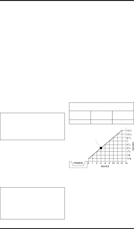
Minimum Clearances For Side Combustible Material, Side Wall and

Ceiling

A. Clearances from the side of the fireplace cabinet to any combustible material and wall should follow diagram in Figure 6.

Example: The face of a mantel, bookshelf, etc. is made of combustible material and protrudes 3 1/2" from the wall. This combus- tible material must be 4" from the side of the fireplace opening (see Figure 6).

B. Clearances from the top of the fireplace opening to the ceiling should not be less than 36 inches.

C. For mantel clearances, see Figure 10 on page 12.

MINIMUM CLEARANCE TO

COMBUSTIBLE MATERIALS

Top

Left and

Bottom and

Right Sides

Rear


36"

6"

0"


Example


*

*Minimum 16 inches from Side Wall

Figure 6 - Minimum Clearance for

Combustible to Wall

10

www.desatech.com

113133-01C

Image 10
Contents Thermostat Models Vdcftna and Vdcftpa Remote-Ready Models Shown with Optional Cabinet Mantel/Hearth Base AccessoryVdcfrpa and Vdcfrna Table of Contents Safety Information Safety Information Product Identification Optional Remote Control AccessoriesProduct Features Local CodesAir for Combustion Ventilation Hood AssemblyTools Required Phillips screwdriver Providing Adequate Ventilation AIR for Combustion VentilationDetermining FRESH-AIR Flow for Fireplace Location Ventilation Air From Inside Building Ventilation AIRVentilation Air From Outdoors Installation Check GAS TypeFireplace Clearances InstallationInstallation Items Fireplace pilot and burner must be at least 18 above floorBuilt-In Fireplace Installation If you have not installed hood, follow instruc- tions onOptional Mantel Installation Route flexible gas line through access hole in hearth baseCheck all gas connections for leaks. See Installing Optional Blower Accessory GA3450TARemoving Upper Louver Remove 4 screws from upper louver see . Save these screws Installing Blower AccessoryOpen lower louver door by swinging door down see Figure For Built-In Installation Extension CordConnecting to GAS Supply External Regulator With Vent Pointing DownInstallation Items Needed Connecting equipment shutoff valve to heater controlChecking GAS Connections Pressure Testing Fireplace Gas Connections Equipment Shutoff ValveRemove battery cover on back of remote control unit Installing ReceiverInstalling 9-Volt Battery in Hand-Held Remote Control Unit Replace battery cover onto remote control unitOptional Wall Switch GWMS2 Remote-Ready Models Only Remove jumper wire from control valve see ,Operating Fireplace Installing LOG SET and ScreenFor Your Safety Read Before Lighting Lighting InstructionsTo Turn OFF GAS To Appliance Manual Lighting ProcedureOperating Fireplace Thermostat Control OperationAUTO/OFF/ON Blower Switch Operating BlowerDepress control knob and light pilot with match On/Off Series Model HRC100 Optional Hand-HeldRemote Operation Thermostat Series Model HRC200Auto Shutoff Feature Optional GWMS2 Wall Mounted SwitchSafety Features Key Pad Lock FeaturePilot Flame Pattern Cleaning MaintenanceInspecting Burners Burner Flame PatternLOG Set Cleaning MaintenanceWiring Diagram CabinetTroubleshooting Observed Problem Possible Cause RemedyTroubleshooting Slight smoke or odor during When heated, vapors fromMote-Ready Models Only Power is low Initial operation Processes and log curingGas leak. See Warning Specifications VDCFTPA, VdcfrpaIllustrated Parts Breakdown Firebox Models VDCParts List Thermostat Models Illustrated Parts BreakdownVdcftpa and Vdcftna Parts List REMOTE-READY Models Vdcfrna and VdcfrpaKEY Equipment Shutoff Valve GA5010 AccessoriesTHERMOSTAT-CONTROLLED Blower KIT GA3450T Receiver and HAND-HELD Thermostat Remote Control KIT HRC200 AccessoriesWALL-MOUNT ON/OFF Switch Receiver and HAND-HELD Remote Control KIT HRC100Technical Service Replacement PartsService Hints Parts Under Warranty113133-01C Keep this Warranty Warranty InformationLimited Warranty VENT-FREE Compact Classic Hearth