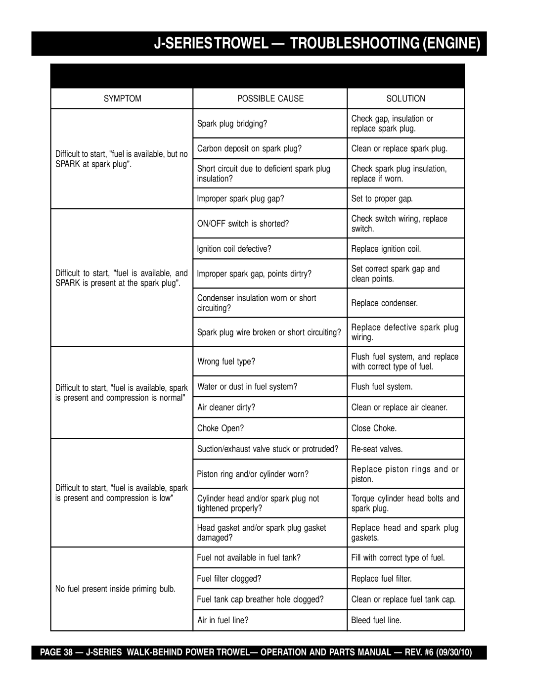
Multiquip J-SERIES manual Trowel Arm Adjustment, Re-Assembly

Page 34

J-SERIESTROWEL — MAINTENANCE

Trowel Arm Adjustment

Shown in Figure 47 is the adjustment fixture with a trowel arm inserted. As each trowel arm is locked into the fixture, the arm bolt is adjusted to where it contacts a stop on the fixture. This will consistently adjust all of the trowel arms, keeping the finisher as flat and evenly pitched as possible.

1.Locate the trowel arm adjustment tool P/N 1817. Set the adjustmenttoolfora clock-wisebladerotation,meaningthe fixture arm is in the "UP" position.

3.Un-screwthelockingboltsontheadjustmenttool,andplace the trowel arm into the adjustment fixture channel as shown inFigure47. Athinshimmayberequiredtocovertheblade holes on the trowel arm. Make sure to align the trowel adjustment bolt with the fixture adjustment bolt.

4.Using an allen wrench, tighten the locking bolts on the adjustment tool and securely lock the trowel arm in place.

5.Loosen the locking nut on the trowel arm lever, then turn the trowel arm adjusting bolt until it barely touches (.010") the adjusting bolt on the fixture.

6.Afterthecorrectadjustmenthasbeenmade,tightenlocknut on trowel arm lever to lock in place.

7.Loosen locking bolts on adjustment fixture, and remove trowel arm from fixture.

8.Repeat steps 2-7 for the remaining trowel arms.

Figure 47. Trowel Arm Adjustment Tool

2.Trowels manufactured prior to June of 1982 require that the distancefromtheendoftheadjustingboltandthefixturearm must be 7/8" (Figure 47).Conversely, trowels manufactured after June of 1982 require that the distance from the end of the adjusting bolt and the fixture arm must be 1/2".

Re-Assembly

1.Clean and examine the upper/lower wear plates and thrust collar.Examine the entire spider assembly.Wire brush any concreteorrustbuild-up.Ifanyofthespider componentsare found to be damaged or out of round, replace them.

2.Makesurethatthebronzetrowelarmbushingisnotdamage or out of round.Clean the bushing if necessary.If the bronze bushing is damage or worn, replace it.

3.Reinstall bronze bushing onto trowel arm.

4.Repeat steps 2 -3 for each trowel arm.

5.Make sure that the spring tensioner is in the correct position to exert tension on the trowel arm.

6.Insertalltrowelarmswithleversintospiderplate(withbronze bushingalreadyinstalled)usingcaretoaligngreaseholeon bronze bushing with grease hole fitting on spider plate.

7.Lock trowel arms in place by tightening the hex head zerk grease fitting and jam nut.

8.Re-install the blades back onto the trowel arms

8.Install stabilizer ring onto spider assembly.

9.Reinstall lower wear plate, thrust collar and upper wear ringinthereverse order thattheyweredis-assembledonto the spider shaft. Make sure that there is little or no lateral movement between the thrust collar and the spider shaft.

PAGE 34 — J-SERIES WALK-BEHIND POWER TROWEL— OPERATION AND PARTS MANUAL — REV. #6 (09/30/10)
Image 34
Contents Series Page Page SERIESTROWEL-TABLE of Contents Best Deal! Order via Internet Dealers Only SERIESTROWEL- Parts Ordering ProceduresOrder via Fax Dealers Only SERIESTROWEL-TRAINING Checklist SERIESTROWEL- Daily PRE-OPERATION Checklist Daily PRE-OPERATION ChecklistSeries TROWEL- Safety Message Alert Symbols Foryour Safety and the Safety of OthersSeries TROWEL- Safety Message Alert Symbols Over Speed Conditions Sight and Hearing hazardSafety SERIESTROWEL- Rules for Safe OperationSERIESTROWEL- Rules for Safe Operation Maintenance SafetyEmergencies SERIESTROWEL- Operation and Safety Decals Machine Safety DecalsSERIESTROWEL- Specifications Trowel SideViewSERIESTROWEL- Specifications Engines & Electric Motor Specifications Engines & Electric MotorSERIESTROWEL- General Information SERIESTROWEL- Controls and Components Series Walk-Behind TrowelsSERIESTROWEL- Controls and Components Guard Ring- NEVER! put hands or feet inside guard ringSERIESTROWEL- Basic Engine Engine Controls and ComponentsAssembly and Installation Seriestrowel Assembly and InstallationHandleTube Installation All Models Pre-load Adjustment Quick Pitch Models Only Seriestrowel Assembly and InstallationThrottle Cable Installation Honda Engine Throttle Wire Hook Safety KillWireBefore Starting SERIESTROWEL- PRE-INSPECTIONEngine Oil Check SERIESTROWEL- PRE-INSPECTION Lifting Bale Option Seriestrowel Initial START-UP Gasoline EngineLifting theTrowel Onto a Slab Auxiliary Lifting Tube Starting the Engine Honda engineCentrifugal Kill Switch Seriestrowel Initial START-UP Gasoline EngineSeriestrowel Initial START-UP Electric Motor Extension CablePitchingThe Blades Quick Pitch Handle Quick Pitch T- Handle Standard HandleSeriestrowel Operation Maneuvering The TrowelClip-On Float Blades Optional Combo BladesSeriestrowel Options Trowel Arm Adjustment ToolGrinding Attachments Daily 8-10 Hours Seriestrowel Maintenance Trowel Arm adjustment Procedure Monthly 200-300 HoursSpider Removal Seriestrowel MaintenanceTrowel Arm Removal Bronze Bushings Trowel Blade Removal Trowel Arm Flatness TestTrowel Arm Adjustment Re-AssemblyHand Clutch Adjustment TestingChanging a Blade Seriestrowel Troubleshooting Trowel TroubleshootingSeriestrowel Troubleshooting Trowel Seriestrowel Troubleshooting Engine Troubleshooting EnginePage Seriestrowel Explanation of Codes in Remarks Column QTY. ColumnSeries Trowel Suggested Spare Parts To 3 UnitsSeriestrowel Nameplate and Decals Seriestrowel Nameplate and Decals Part Name QTY RemarksSeriestrowel Standard Handle Assy Handle Grip Seriestrowel Quick Pitch Handle Assy Quick Pitch Trigger Seriestrowel -THRUST Bearing KIT Assy Wear Ring Seriestrowel 3 and 4-BLADE Spider Assy Part NO. Part Name Seriestrowel Gearbox and Engine Mounts Assy Gear Case Seriestrowel ENGINES, 5.0 HP HONDA,4.6 HP ROBIN, 3&5 HPB&S Part Name Seriestrowel Hand Clutch ASSY. S/N LJ42036 and below Hand Clutch ASSY.-S/N LJ42036 and below Series Trowel Hand Clutch ASSY. S/N LJ42037 and Above Part Name QTY Seriestrowel Electric Motor Assy Electric Motor 2HP Seriestrowel Guard Ring Assy Guard Ring Assy Seriestrowel Blades & Adjustment Fixture Assy Guard Ring Seriestrowel Lifting Bale ASSY. Option Lock Washer 3/8 Honda GX160K1QA2 Engine Cylinder Head Assy GUIDE, IN. Valve Over Size Honda GX160K1QA2 Engine Cylinder Barrel Assy WEIGHT, Governor Honda GX160K1QA2 Engine Crankcase Cover Assy Gasket Case Cover Honda GX160K1QA2 Engine Crankshaft Assy 13310ZE1601 Honda GX160K1QA2 Engine Piston Rings Assy Piston Rings Assy Honda GX160K1QA2 Engine Camshaft Assy ROD, Push Honda GX160K1QA2 Engine Recoil Starter Assy REEL, Recoil Starter Honda GX160K1QA2 Engine FAN Cover Assy PLATE, Sidestd Honda GX160K1QA2 Engine Carburetor Assy Gasket SET Honda GX160K1QA2 Engine AIR Cleaner OIL Bath Assy Gasket Elbow Honda GX160K1 Engine Muffler Assy Muffler Comp Honda GX160K1QA2 Engine Fueltank Assy RUBBER, Supporter Honda GX160K1QA2 Engine Flywheel Assy FAN, Cooling Honda GX160K1QA2 Engine Ignition Coil Assy Coil ASSY., Ignition Honda GX160K1QA2 Engine Control Assy ARM, Governor Honda GX160K1QA2 Engine Label Assy EMBLEM, Internal Page Honda GX160K1QA2 Engine Gasket KIT Assy Gasket KIT AssyTerms and Conditions of Sale Parts Page HERE’S HOW to GET Help