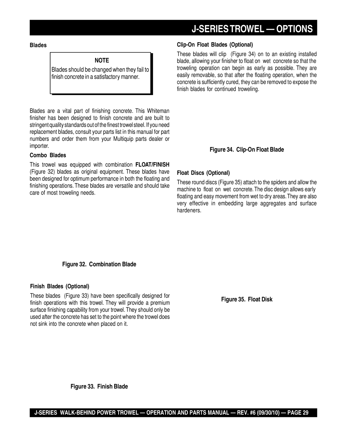
Multiquip J-SERIES manual Testing, Changing a Blade, Hand Clutch Adjustment

Page 35

J-SERIESTROWEL — MAINTENANCE

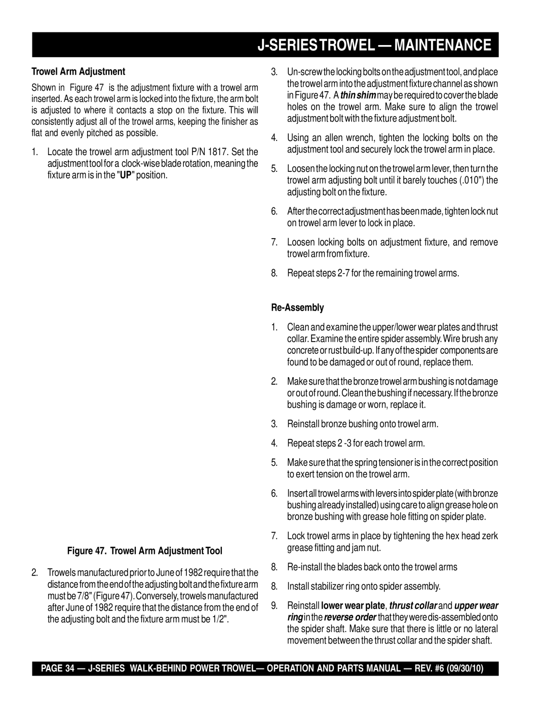
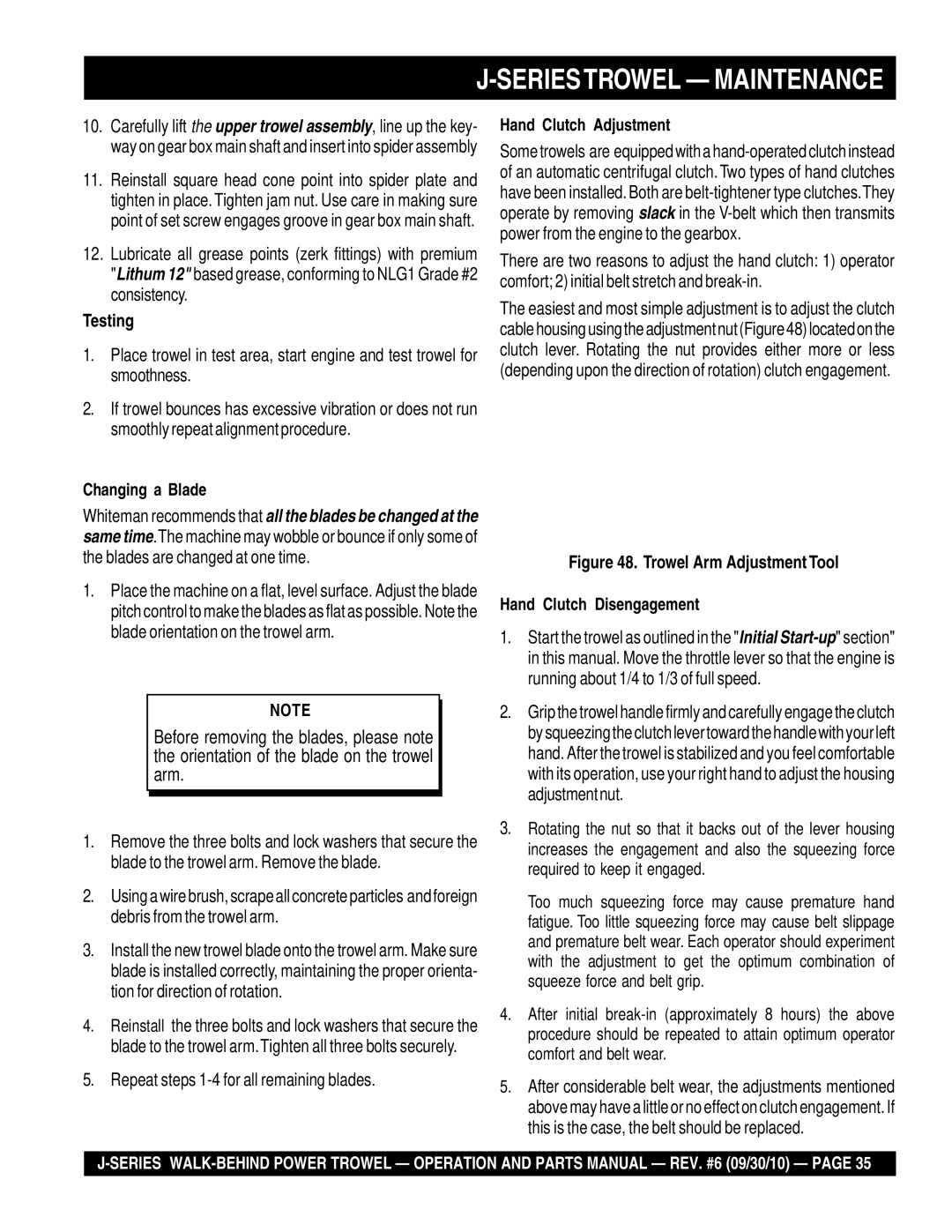
10.Carefully lift the upper trowel assembly, line up the key- way on gear box main shaft and insert into spider assembly

11.Reinstall square head cone point into spider plate and tighten in place.Tighten jam nut. Use care in making sure point of set screw engages groove in gear box main shaft.

12.Lubricate all grease points (zerk fittings) with premium "Lithum 12" based grease, conforming to NLG1 Grade #2 consistency.

Testing

1.Place trowel in test area, start engine and test trowel for smoothness.

2.If trowel bounces has excessive vibration or does not run smoothly repeat alignment procedure.

Changing a Blade

Whiteman recommends that all the blades be changed at the same time.The machine may wobble or bounce if only some of the blades are changed at one time.

1.Place the machine on a flat, level surface. Adjust the blade pitch control to make the blades as flat as possible. Note the blade orientation on the trowel arm.

NOTE

Before removing the blades, please note the orientation of the blade on the trowel arm.

1.Remove the three bolts and lock washers that secure the blade to the trowel arm. Remove the blade.

2.Usingawirebrush,scrapeallconcreteparticles andforeign debris from the trowel arm.

3.Install the new trowel blade onto the trowel arm. Make sure blade is installed correctly, maintaining the proper orienta- tion for direction of rotation.

4.Reinstall the three bolts and lock washers that secure the blade to the trowel arm.Tighten all three bolts securely.

5.Repeat steps 1-4 for all remaining blades.

Hand Clutch Adjustment

Sometrowels are equippedwithahand-operatedclutchinstead of an automatic centrifugal clutch. Two types of hand clutches have been installed.Both are belt-tightener type clutches.They operate by removing slack in the V-belt which then transmits power from the engine to the gearbox.

There are two reasons to adjust the hand clutch: 1) operator comfort; 2) initial belt stretch and break-in.

The easiest and most simple adjustment is to adjust the clutch cablehousingusingtheadjustmentnut(Figure48)locatedonthe clutch lever. Rotating the nut provides either more or less (depending upon the direction of rotation) clutch engagement.

Figure 48. Trowel Arm Adjustment Tool

Hand Clutch Disengagement

1.Start the trowel as outlined in the "Initial Start-up" section" in this manual. Move the throttle lever so that the engine is running about 1/4 to 1/3 of full speed.

2.Gripthetrowelhandlefirmlyandcarefullyengagetheclutch bysqueezingtheclutchlevertowardthehandlewithyourleft hand. After the trowel is stabilized and you feel comfortable with its operation, use your right hand to adjust the housing adjustmentnut.

3.Rotating the nut so that it backs out of the lever housing increases the engagement and also the squeezing force required to keep it engaged.

Too much squeezing force may cause premature hand fatigue. Too little squeezing force may cause belt slippage and premature belt wear. Each operator should experiment with the adjustment to get the optimum combination of squeeze force and belt grip.

4.After initial break-in (approximately 8 hours) the above procedure should be repeated to attain optimum operator comfort and belt wear.

5.After considerable belt wear, the adjustments mentioned above may have a little or no effect on clutch engagement. If this is the case, the belt should be replaced.
J-SERIES WALK-BEHIND POWER TROWEL — OPERATION AND PARTS MANUAL — REV. #6 (09/30/10) — PAGE 35

Image 35
Contents Series Page Page SERIESTROWEL-TABLE of Contents Order via Fax Dealers Only SERIESTROWEL- Parts Ordering ProceduresBest Deal! Order via Internet Dealers Only SERIESTROWEL-TRAINING Checklist Daily PRE-OPERATION Checklist SERIESTROWEL- Daily PRE-OPERATION ChecklistForyour Safety and the Safety of Others Series TROWEL- Safety Message Alert SymbolsOver Speed Conditions Sight and Hearing hazard Series TROWEL- Safety Message Alert SymbolsSERIESTROWEL- Rules for Safe Operation SafetyEmergencies Maintenance SafetySERIESTROWEL- Rules for Safe Operation Machine Safety Decals SERIESTROWEL- Operation and Safety DecalsSideView SERIESTROWEL- Specifications TrowelSpecifications Engines & Electric Motor SERIESTROWEL- Specifications Engines & Electric MotorSERIESTROWEL- General Information Series Walk-Behind Trowels SERIESTROWEL- Controls and ComponentsGuard Ring- NEVER! put hands or feet inside guard ring SERIESTROWEL- Controls and ComponentsEngine Controls and Components SERIESTROWEL- Basic EngineHandleTube Installation All Models Seriestrowel Assembly and InstallationAssembly and Installation Throttle Cable Installation Honda Engine Seriestrowel Assembly and InstallationPre-load Adjustment Quick Pitch Models Only Safety KillWire Throttle Wire HookEngine Oil Check SERIESTROWEL- PRE-INSPECTIONBefore Starting SERIESTROWEL- PRE-INSPECTION Starting the Engine Honda engine Seriestrowel Initial START-UP Gasoline EngineLifting theTrowel Onto a Slab Auxiliary Lifting Tube Lifting Bale OptionSeriestrowel Initial START-UP Gasoline Engine Centrifugal Kill SwitchExtension Cable Seriestrowel Initial START-UP Electric MotorQuick Pitch T- Handle Standard Handle PitchingThe Blades Quick Pitch HandleManeuvering The Trowel Seriestrowel OperationCombo Blades Clip-On Float Blades OptionalGrinding Attachments Trowel Arm Adjustment ToolSeriestrowel Options Monthly 200-300 Hours Seriestrowel MaintenanceTrowel Arm adjustment Procedure Daily 8-10 HoursTrowel Arm Removal Seriestrowel MaintenanceSpider Removal Trowel Arm Flatness Test Bronze Bushings Trowel Blade RemovalRe-Assembly Trowel Arm AdjustmentChanging a Blade TestingHand Clutch Adjustment Troubleshooting Seriestrowel Troubleshooting TrowelSeriestrowel Troubleshooting Trowel Troubleshooting Engine Seriestrowel Troubleshooting EnginePage QTY. Column Seriestrowel Explanation of Codes in Remarks ColumnTo 3 Units Series Trowel Suggested Spare PartsSeriestrowel Nameplate and Decals Part Name QTY Remarks Seriestrowel Nameplate and DecalsSeriestrowel Standard Handle Assy Handle Grip Seriestrowel Quick Pitch Handle Assy Quick Pitch Trigger Seriestrowel -THRUST Bearing KIT Assy Wear Ring Seriestrowel 3 and 4-BLADE Spider Assy Part NO. Part Name Seriestrowel Gearbox and Engine Mounts Assy Gear Case Seriestrowel ENGINES, 5.0 HP HONDA,4.6 HP ROBIN, 3&5 HPB&S Part Name Seriestrowel Hand Clutch ASSY. S/N LJ42036 and below Hand Clutch ASSY.-S/N LJ42036 and below Series Trowel Hand Clutch ASSY. S/N LJ42037 and Above Part Name QTY Seriestrowel Electric Motor Assy Electric Motor 2HP Seriestrowel Guard Ring Assy Guard Ring Assy Seriestrowel Blades & Adjustment Fixture Assy Guard Ring Seriestrowel Lifting Bale ASSY. Option Lock Washer 3/8 Honda GX160K1QA2 Engine Cylinder Head Assy GUIDE, IN. Valve Over Size Honda GX160K1QA2 Engine Cylinder Barrel Assy WEIGHT, Governor Honda GX160K1QA2 Engine Crankcase Cover Assy Gasket Case Cover Honda GX160K1QA2 Engine Crankshaft Assy 13310ZE1601 Honda GX160K1QA2 Engine Piston Rings Assy Piston Rings Assy Honda GX160K1QA2 Engine Camshaft Assy ROD, Push Honda GX160K1QA2 Engine Recoil Starter Assy REEL, Recoil Starter Honda GX160K1QA2 Engine FAN Cover Assy PLATE, Sidestd Honda GX160K1QA2 Engine Carburetor Assy Gasket SET Honda GX160K1QA2 Engine AIR Cleaner OIL Bath Assy Gasket Elbow Honda GX160K1 Engine Muffler Assy Muffler Comp Honda GX160K1QA2 Engine Fueltank Assy RUBBER, Supporter Honda GX160K1QA2 Engine Flywheel Assy FAN, Cooling Honda GX160K1QA2 Engine Ignition Coil Assy Coil ASSY., Ignition Honda GX160K1QA2 Engine Control Assy ARM, Governor Honda GX160K1QA2 Engine Label Assy EMBLEM, Internal Page Gasket KIT Assy Honda GX160K1QA2 Engine Gasket KIT AssyTerms and Conditions of Sale Parts Page HERE’S HOW to GET Help