Telex C-2002 technical manual Front Panel, Common Controls and Indicators

Page 8

2

Vega’s C-2002

2 Controls and Indicators


C-2002


Vu Muter

11:08AM


Ln1-Fn2

Ln2-Fn8


1

2

3

A

F1

F2

SUP


ABC

DEF

->

4

5

6

B

F3

F4

Alert

GHI

JKL

MNO

<-

7

8

9

C

F5

F6

Chan

PQRS

TUV

WXYZ

<sp>


*

0

#

D

F7

F8

ALT

Enter


LINE 1


LINE 2


Mute

RLS

SEL

Mute

RLS

SEL

VOLUME

MON

IC

Transmit


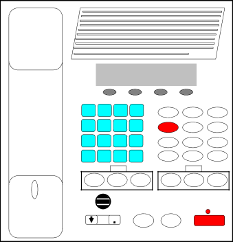
Figure 1 Front Panel Diagram

2.1Front Panel

Figure 1 shows a view of the Front panel. The Front panel contains the user I/O. It features a Volume control, intercom and monitor functions, panel PTT with indicator, built in panel microphone, per line Select, Release and Mute functions, DTMF keypad, Supervisory, Alert, Channel and ALT functions used with the F1-F8 Function Tone selection. The C-2002 is programmed from the front panel using the four gray soft keys located below the Vacuum Florescent LCD display provides channel/numeric indication, clock and audio-level meter.

2.1.1Common Controls and Indicators

VU Meter: Displays Selected receive and Microphone audio bus levels. This meter is shown on the top line of the display and utilizes the first 12 display elements from the upper left.

Program 1-4:Are used as “soft” programming buttons when in the tech mode. These buttons will have different functions depending on the action required. The bottom line of the display will show their respective functions.

DTMF Keypad: The DTMF keypad is used for transmitting DTMF digits, selecting frequencies for tone control in tech mode (section 6), and entering alphanumeric strings for line/function tone combinations.

Function Buttons F1-F8:When a function tone button is pressed, a guard tone and function tone burst is sent out. No hold tone is associated with the changing of the function tone. When one of the function tones is selected it will light to indicate which function tone is chosen, a function tone shall remain selected until the operator changes the setting. The console will power up with the last selected line and function tone pair selected.

Supervisory button: The SUP button allows one console operator to disable any other console, which is connected to the supervised line. The Red LED is on during supervisory and blinking when being supervised

Alert button: When pressed, a alert tone plus key–up tones will be sent to all Selected lines.

Channel button: Used to change selected line F-tone frequency via the DTMF keypad.

ALT button: Used as a Alternate or Shift function for F1-8 and Alert tones.

Image 8
Contents Model C-2002 Radio Control Console Technical Manual Page Table of Contents Vega’s C-2002 Iii Default Shipping Configuration Introduction Front Panel Controls and IndicatorsCommon Controls and Indicators Rear Panel Connections Rear Panel PortsRear Panel Connector Pinouts Rear Panel PinoutOperation Line Setup and Description CrossmuteTwo-Wire/Four-Wire Mode RX Side SettingsSupervisor Function Relay Contact Closure For Local ControlTX Side Settings Transmit MonitorLevel Adjustments Transmit Side AdjustmentsTransmit Monitor Setup RX Level AdjustmentLine Interface Hardware OverviewC-2002 Console Theory of Operation Microphone Input PathsAudio Output Paths Line Receive Paths Line One/TwoClone Mode Serial Port Power Regulation and Reset Control System Clock GenerationNon-Volatile Memory Eeprom User I/OSetup Mode Tech ModeRestore Defaults? Erasing all settingsOpening Display Menu AUXLevel Menu Screen Button Activated Setup ModesOpening menu Line 1 level adjust Ln1 Min Rx lvl -60dB60dB dwn Back LAM1-S 7sec -10dBm dur lvl S/U backMain level adjust MIC Spkr TX back Main Mic adjustMute Level = -10dB 10db dwn BackSystem Settings Screen Main tone Adjust Dtmf Tone Back Working…Please Wait Target Not Found Dump backDtmf Keypad Enable Tgl Dtmf Hold = 500msec 500ms dwn up back100/100 OffLevel 10/0/-20 Guard FTn Hold back Tone Settings Lvl Freq Dur backDtmf RX Hold Sec Edit Next AUX Input Enabled Tglback AUX Input EnableGrd&Hld Freq= 2175Hz Prev next back Duration 130/200 Guard Hold BackSystem Settings PIN Txdel next back PIN Setup NewTX Delay 300msec New PINAlphanumeric Function-Line Setup L1 F? Back ? F1 BackRampart Line/F-Tone Selection ScreenLine Tone/Local Screen Mute Button Function Tone Parameter Screen Supervisor Enable Alert ProgrammingMonitor Programming Screen Section Parameter Default Programmed Vega’s C-2002 Remote Control Console C-2002 Top Assembly, P.N Schematic Bill of Material, component layoutTechnical Documentation C-2002 Main Board, P/NPage Page Page Page Page Page Page Page PCB ASSY, C-2002 Main Board QTY Type Description Designator Conn SMT 40 PIN Type Description Designator Page BNSFRDCKeypad.sch-1 Fri Mar 22 131105 PCB ASSY, Bnsf RDC Keypad Board Page Page Doug Ehlers Factory Service Center Telex Communications, Inc Warranty, Service, Repair, and CommentsWarranty Limited Specifications Front panel controls