Lincoln Electric manual V160-S Wiring Diagram, Wiring Diagram Code

Page 25

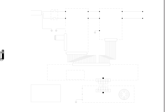
WIRING DIAGRAM CODE 11031

V160-S WIRING DIAGRAM

WHITE 2

1

BLUE

DC+

RED

W1


AC1

DC+

F-2

115/230/1/50/60

Vac

BLACK 4

3

BROWN

DC-A

BLACK

W2


AC2

DC-

+

S1

GREEN

OR

YELLOW / GREEN

FAN

INPUT BOARD

GND W05X0250

(SCHEMATIC:

X0203)

1

2

JP2

3

4

JP1

INVERTER BOARD


W05X0190

Y/G


(SCHEMATIC:


X0190)


GND


JP1


1

2

3

4

5

6

7

8

9 10

-

V160-S

1 2 3 4 5 6 7 8 9 10 11 12 13 14 15 16

DISPLAY BOARD

W05X0371

(SCHEMATIC: X0371)

26

25 24

23

22

21

20

19 18 17 16 15 14 13 12

11

10 9

8

7

6

5

4

3

2

1

J1

WELD CONTROLLER

W05X0338

(SCHEMATIC: X0233)

JP1

WARNING: HIGH VOLTAGE CAN KILL

*Do not operate with covers removed.

*Disconnect input power by unplugging power cord before servicing.

*Do not touch electrically live parts.

*Only qualified persons should install, use or service this machine.

*

Y/G

*

J1

REMOTE BOARD

EARTH W05X0322

(SCHEMATIC: X0322)

W07X0261rev03

DIAGRAMS

RIBBON CABLE

NOTE: This diagram is for reference only. It may not be accurate for all machines covered by this manual. The specific diagram for a particular code is pasted inside the machine on one of the enclosure panels. If the diagram is illegible, write to the Service Department for a replacement. Give the equipment code number.

F-2

Image 25
Contents Invertec V160-S California Proposition 65 Warnings SafetyElectric Shock can kill Iii Welding Sparks can cause fire or explosionSûreté Pour Soudage a LʼArc Précautions DE SûretéThank You Table of Contents Technical Specification V160-S InstallationOperating Temperature Range Storage Temperature RangeInput Connections Safety PrecautionsSelect Suitable Location Ground Connection230V Input Arfu AUTO-RESTORE Fuse115V Input Attachment PlugOutput Connection for Stick Welding Figure A.2 Output and GAS Connection for TIG Welding Figure A.1Quick Disconnect Plug for Stick ELEC- Trode Cable Remote Control ConnectionOutput Connection for TIG Welding Operation Safety InstructionsGeneral Description Welding CapabilityPower Switch Fan V160-S Controls and Settings See Figure B.2Rear Control Panel Power LED Mode SwitchArc Control Thermal LEDDIP Switch 1 Machine Type DIP Switch FunctionsDIP Switch 2 thru 5 non-functional for the V160-S Electric Shock can KillDIP Switch 1 = on DIP Switch 6 European/USA Machine ConfigurationDIP Switch 7 thru 8 non-functional for the V160-S START/CRATER Current AdjustmentOptional Accessories AccessoriesCompatible Equipment Cable PlugsSafety Precautions MaintenanceInput Filter Capacitor Discharge Procedure Routine MaintenanceHOW to USE Troubleshooting Guide TroubleshootingTroubleshooting Troubleshooting Troubleshooting Wiring Diagram Code DiagramsWiring Diagram Code V160-S Wiring DiagramV160-S Precaucion Warnung