Craftsman 919.167242 How to Stop, Before Starting Break-in Procedure, Drain Valve, Check Valve

Page 14

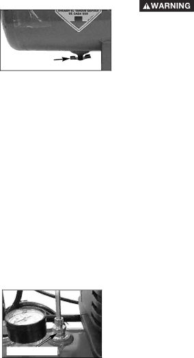
Drain Valve: The drain valve is located at the base of the air tank and is used to drain condensation at the end of each use.

Drain

Valve

Cooling System (not shown): This compressor contains an advanced design cooling system. At the heart of this cooling system is an engineered fan. It is perfectly normal for this fan to blow air through the vent holes in large amounts. You know that the cooling system is working when air is being expelled.

Air Compressor Pump (not shown): Compresses air into the air tank. Working air is not available until the compressor has raised the air tank pressure above that required at the air outlet.

Check Valve: When the air compressor is operating, the check valve is "open", allowing compressed air to enter the air tank. When the air compressor reaches "cut-out" pressure, the check valve "closes", allowing air pressure to remain inside the air tank.

Check Valve

How to Use Your Unit

How to Stop:

1.Set the On/Auto/Off lever to "OFF".

Before Starting

Break-in Procedure

Risk of Unsafe Operation. Serious

damage may result if the following break-in instructions are not closely followed.

This procedure is required before the air compressor is put into service and when the check valve or a complete compressor pump has been replaced.

1.Make sure the On/Auto/Off lever is in the "OFF" position.

NOTE: Pull coupler back until it clicks to prevent air from escaping through the quick connect.

2.Plug the power cord into the correct branch circuit receptacle. (Refer to Voltage and Circuit Protection paragraph in the Installation section of this manual.)

3.Open the drain valve fully (counter-clockwise) to permit air to escape and prevent air pressure build up in the air tank during the break-in period.

4.Move the On/Auto/Off lever to "ON/AUTO" position. The compressor will start.

5.Run the compressor for 15 minutes. Make sure the drain valve is open and there is minimal air pressure build-up in tank.

6.After 15 minutes, close the drain valve (clockwise). The air receiver will fill to "cut-out" pressure and the motor will stop.

The compressor is now ready for use.

A08598

14- ENG

Image 14
Contents AIR Compressor Table of Contents Important Safety Instructions Specification ChartSafety Guidelines Definitions Location away from compressor Spray area. An additional length of hoseExplosion May be required Fire, do not allow the compressor toAttachments & Accessories What Could HappenElectrical codes Safety equipment must be properlyAccordance with national and local Electrical Grounding Failure to provideHot for several minutes after operation Or attempt maintenance until unit hasResult in serious burns Do not reach around protective shroudsHazard Glossary AccessoriesAccessories Duty CycleTools Required for Assembly AssemblyContents of Carton Installing Handles Wheels, and Molded Foot BumpersGrounding Instructions InstallationLocation of the Air Compressor Plug Grounded Outlets Grounding PinExtension Cords Voltage and Circuit ProtectionDescription of Operation OperationKnow Your Air Compressor RegulatorDrain Valve How to StopBefore Starting Break-in Procedure Check ValveHow to Start Before Each Start-UpCustomer Responsibilities MaintenanceTo Check Safety Valve To Drain TankOutlet Tube Nut Check Valve Service and AdjustmentsTo Replace or Clean Check Valve Screwdriver Open position nothing is visibleRegulator Arrow StorageTo Replace Regulator Troubleshooting Pressure reading Problem Cause Correction Garantía Total DE UN AÑO DEL Compresor DE Aire ContenidoGarantía Resultar en lesiones menores o Definiciones DE Normas DE SeguridadModelo Nº 919.167242 ModeradasCómo prevenirlo Instrucciones Importantes DE SeguridadGuarde Estas Instrucciones Advertencia Riesgo de Explosión Qué puede occurrir Cómo prevenirloA08598 30- SP Advertencia Riesgo de Quemaduras Qué puede occurrir Advertencia Riesgo de Caída Qué puede occurrirAdvertencia Riesgo de Operación Insegura Qué puede occurrir Ciclo DE Servicio GlosarioAccesorios AccesoriosHerramientas requeridas para el ensamblado EnsambladoContenido del embalaje Instalación de manijas, ruedas y pie moldeado de reboteUbicación del compresor de aire InstalaciónCómo Preparar LA Unidad Cables de extensión eléctrica Protección del voltaje y del circuitoDescripción de operaciones OperaciónConozca su compresor de aire Presión de salida TanqueCómo detenerla Cómo utilizar su unidadAntes de poner en marcha Antes de cada puesta en marcha Cómo poner en marchaCómo verificar la válvula de seguridad MantenimientoResponsabilidades del cliente Cómo drenar el tanqueTubo de salida Tuerca Servicio Y AjustesPara reemplazar o limpiar la válvula reguladora Destornillador En posición abierta nada es visiblePara reemplazar el regulador Regulador FlechaAlmacenaje Riesgo Guía DE Diagnóstico DE ProblemasProblema Causa Corrección Alguna porque se debilitaráDesciende cuando El motor no funciona Product replacement if your covered product cant be fixed Repair Protection AgreementsGet it fixed, at your home or ours