Delta 36-978 instruction manual Using Auxiliary Wood Facing, Fig. S18

Page 32

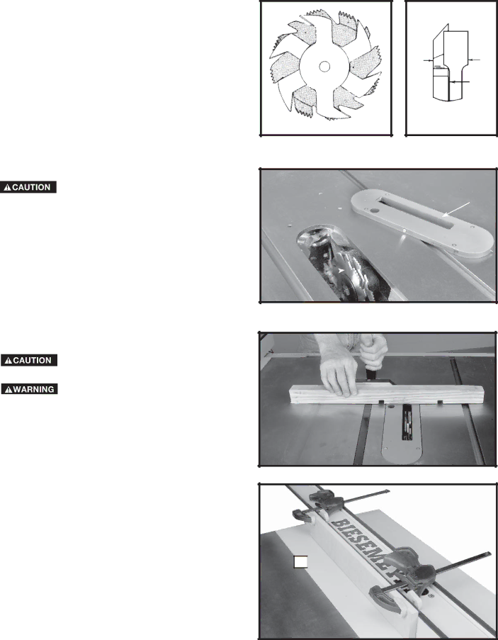
1.Dadoing is cutting a rabbet or wide groove into the work. Most dado head sets are made up of two outside saws and four or five inside cutters, (Fig.

S17). Various combinations of saws and cutters are used to cut grooves from 1/8to 13/16for use in shelving, making joints, tenoning, grooving, etc. The cutters are heavily swaged and must be arranged so that the teeth do not hit each other during rotation. The heavy portion of the cutters should fall in the gullets of the outside saws, as shown in Fig. S18. The saw and cutter overlap is shown in Fig. S19

(A)being the outside saw, (B) an inside cutter, and

(C)a paper washer or washers, used as needed to control the exact width of groove. A 1/4"groove is cut by using the two outside saws. The teeth of the saws should be positioned so that the raker on one saw is beside the cutting teeth on the other saw.

DO NOT ATTEMPT TO STACK DADO BLADES THICKER THAN 13/16” (20MM)

DO NOT USE DADO BLADES LARGER THAN 8” (200MM) IN DIAMETER.

2.Attach the dado head set (D) Fig. S20, to the saw arbor. NOTE: IF THE ARBOR NUT DOES NOT FULLY

ENGAGE THE THREAD ON THE ARBOR, REMOVE THE OUTSIDE ARBOR FLANGE AND TIGHTEN THE ARBOR NUT AGAINST THE DADO HEAD SET BODY. DO NOT LOSE THE OUTSIDE ARBOR FLANGE. IT WILL BE NEEDED WHEN REATTACHING A BLADE TO THE ARBOR.

3.Fig. S21, shows a typical dado operation using the miter gauge as a guide.

NEVER USE THE DADO HEAD IN A

BEVEL POSITION.

ALWAYS INSTALL BLADE GUARD AND

STANDARD TABLE INSERT AFTER OPERATION IS COMPLETED.

USING AUXILIARY WOOD FACING

It is necessary when performing special operations such as when using the moulding cutterhead to add wood facing (A) Fig. S22, to one or both sides of the rip fence. Depending on the fence, the wood facing is attached to the fence either with wood screws through holes drilled in the fence or with two clamps (as shown in Fig. S22). For most work, 3/4" stock is suitable, although an occasional job may require one-inch facing.

AB

C

Fig. S18

Fig. S19

E

D

Fig. S20

Fig. S21

A

Fig. S22

32

Image 32
Contents Contractor’s Saw Model 36-979 Shown With Model 36-B30 Fence SystemTable of Contents Important Safety InstructionsSafety Guidelines Tool Warning LabelsGeneral Safety Rules Important Safety InstructionsAdditional Specific Safety Rules Some Materials are TOO HardGrounding Instructions Power ConnectionsMotor Specifications Volt Single Phase Operation Extension CordsCarton Contents Functional DescriptionExtension Wings Stand and Mobile Base PartsSheet Metal Extension Wings Cast Iron Extension WingsAssembly Unpacking and CleaningAssembly Tools Required Assembly Time EstimateMobile Base and Stand Assembly Front and Side PanelsShort and Long LEG Supports Corner BracketsAttaching Foot Lever Assembly to Base Open END is Aligned AS Shown in FigsAS Shown in FIG Leveling Feet WheelsMobile Base and Stand Assembly to SAW Dust Chute and Back BraceBlade Tilting Raising Handwheel Wrench HookMotor to Motor Mounting Plate E FMotor and Motor Mounting Plate to SAW Motor PULLEY, Pulley GUARD, and Drive BeltTo the Arbor Pulley Connecting Motor Cord to Switch Assembly Removing Motor for TransportBlade Guard and Splitter Assembly and Alignment Assemble the blade guard and splitter assembly Model 36-978 only Model 36-979 onlyON/OFF Switch Locking Switch in the OFF PositionOperation Starting and Stopping SAWDisconnect Machine from Power Source Overload ProtectionRaising and Lowering Blade Tilting the BladeMiter Gauge Operation and Adjustment Adjusting Table InsertAssembling Miter Gauge Table Insert a should Always be Level with the TableAligning Miter Slots to Blade Changing the SAW BladeQuick Operations Checklist Machine USEKEY Parts and Safety Features on Your SAW Back ViewBlade Guard and Splitter USE CROSS-CUTTINGNever USE the Fence AS a CUT-OFF Gauge When CROSS-CUTTING MiteringBevel Crosscutting Compound MiteringRipping Constructing a Push StickUsing Moulding Cutterhead Bevel RippingUsing Accessory Dado Head Fig. S15Using Auxiliary Wood Facing Fig. S18Constructing a Featherboard TroubleshootingPower Tool Institute Push Stick Constructing a Push StickMaintenance Shelf MeasurementsWarranty ServiceAccessories Delta Machinery
Related manuals
Manual 100 pages 12.32 Kb