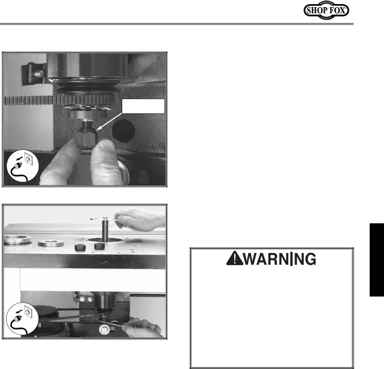
Grizzly w1702 instruction manual Threading drawbar nut onto drawbar

Page 17

Drawbar Nut

Taper Side Up

Figure 20. Threading drawbar nut onto drawbar.

Figure 21. Tightening the drawbar nut onto the

end of the drawbar.

6.Thread the tapered drawbar nut onto the end of the drawbar under the table, and make sure that the taper side of the nut is facing upward as shown in Figure 20.

7.Tighten your selected spindle in the shaper as outlined below:

For shaper spindles: Place the spindle wrench on the top end of the spindle. Using a 15mm open-end wrench, tighten the drawbar nut while holding the spindle wrench secure as shown in Figure 21. DO NOT over-tighten the drawbar nut.

For router bit spindles: Hold the router bit spindle flat on the shank—NOT the collet nut. Using a 15mm open-end wrench, tighten the drawbar nut while holding the router bit spindle in position with a wrench. DO NOT over-tighten the drawbar nut.

ONLY operate your shaper in the COUNTER- CLOCKWISE direction as looking downward at the spindle when when you use a router bit adapter. Router bits are designed to cut in the counter-clockwise direction only. DO NOT operate the shaper in the clockwise direction to make any sort of router-bit back cut. If this caution is ignored, the workpiece can kick back, or the collet can loosen and throw the cutter causing severe injury or death!

ASSEMBLY

-15-

Image 17
Contents HP Shaper Page Contents About Your New Shaper Woodstock Service and SupportIntroduction Specifications Warranty and ReturnsStandard Safety Instructions SafetySafety Additional Safety Instructions for Shapers Use a Shop FOX Featherboard as Avoiding Potential Injuries220V Operation ElectricalExtension Cords GroundingInventory AssemblyUnpacking Beginning Initial CleaningShop Preparation Dust CollectionAuxiliary Guard Safety GuardFence Facing To install the crank handle, do these steps To install the hold-downs, do these stepsHold-Downs HandwheelUnplug the Shaper SpindleThreading drawbar nut onto drawbar Fence Positioning AdjustmentsTo adjust the fence, do these steps Fence Alignment Table Inserts To adjust the table inserts, do these stepsTo align the pulleys, do these steps Pulley AlignmentTo change the spindle RPM, do these steps Spindle RPMChoose Spindle RPM To check the spindle slide-to-gib clearance, do these steps Spindle Slide and GibStart Up OperationsCutter Direction Forward and reverse switchChoose Cutter Profile and Cutter Cutter InstallationChoose Cutter Height and Spindle Size Choose Spindle and Cutter RPMPlace the spindle washer onto the spindle as shown in Figure To set the spindle height, do these steps Setting Spindle HeightStraight Shaping Operations Rub Collars There are three set up positions for rub collarsStarting pin operation Guard not shown for clarity Freehand ShapingTo make a template, do these steps Pattern ShapingGeneral MaintenanceTable and Base LubricationTroubleshooting Closure Model W1702 220V Wiring Diagram Parts Stand Parts Handle Parts XPR15M Parts XPW02 Lock Washer 3⁄8 Parts Miter Gauge Body HOLD-DOWN BAR Shaper Accessories Shaper Accessories Your Notes Your Notes Warranty Card BOX BELLINGHAM, WA