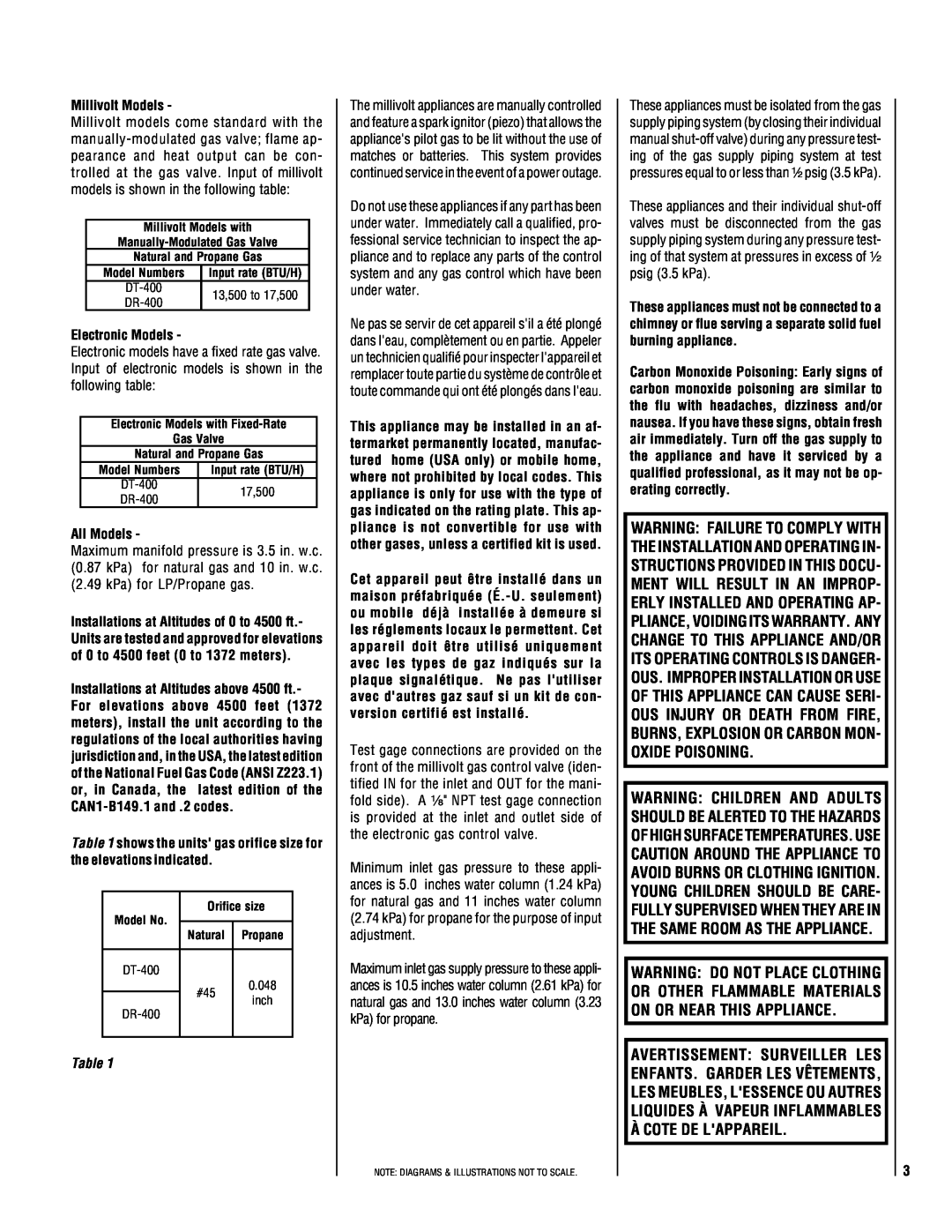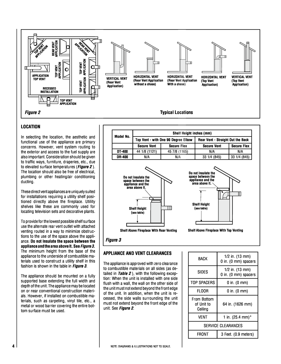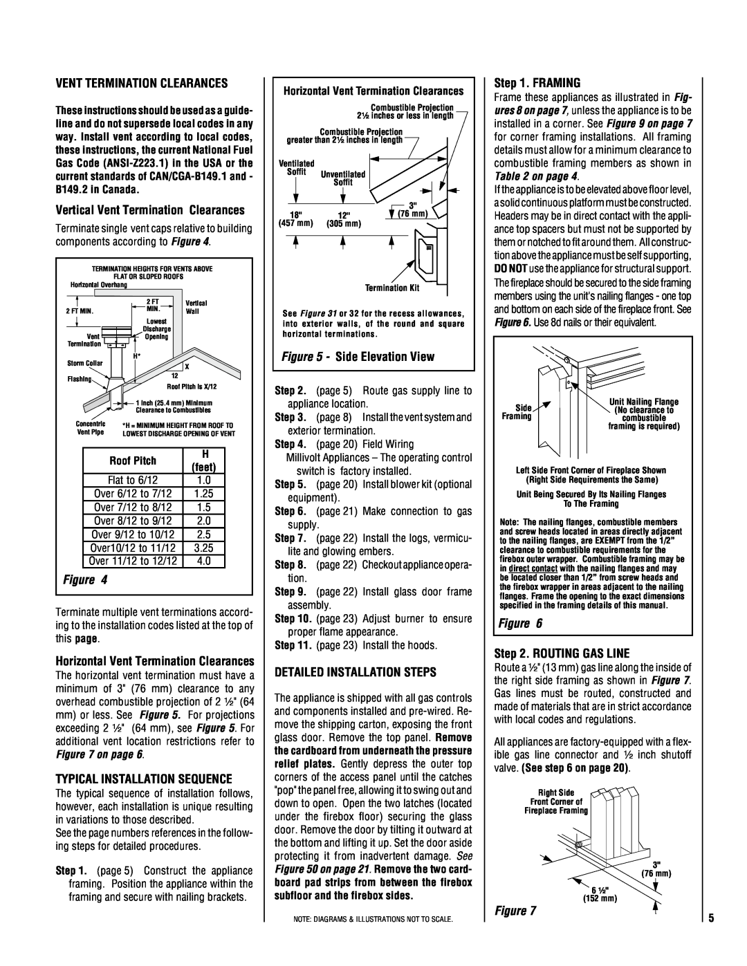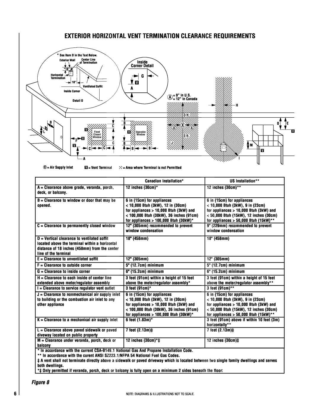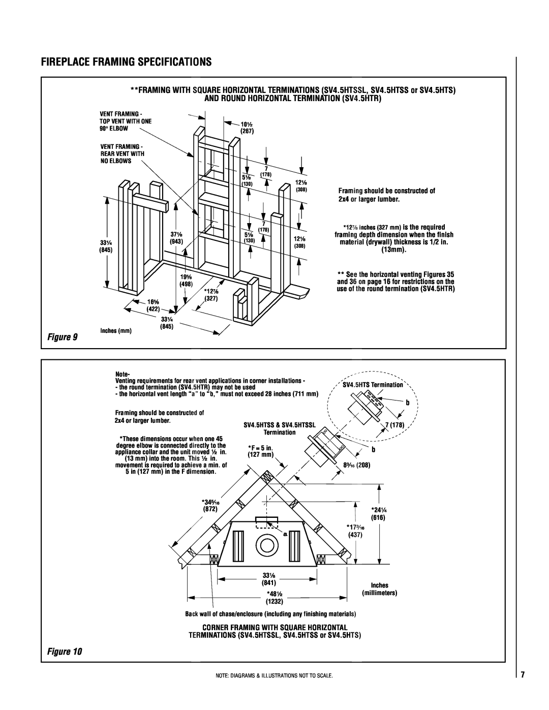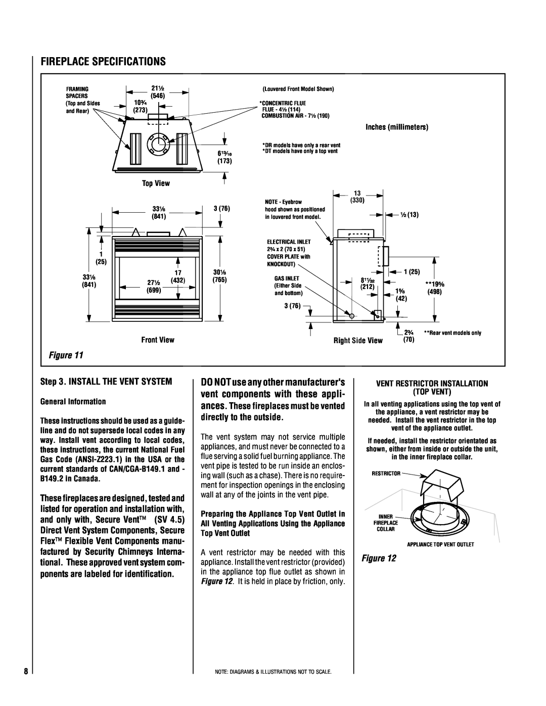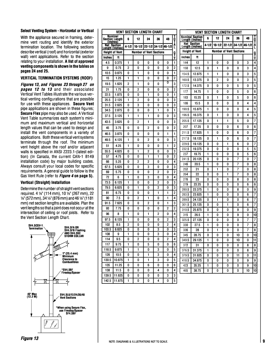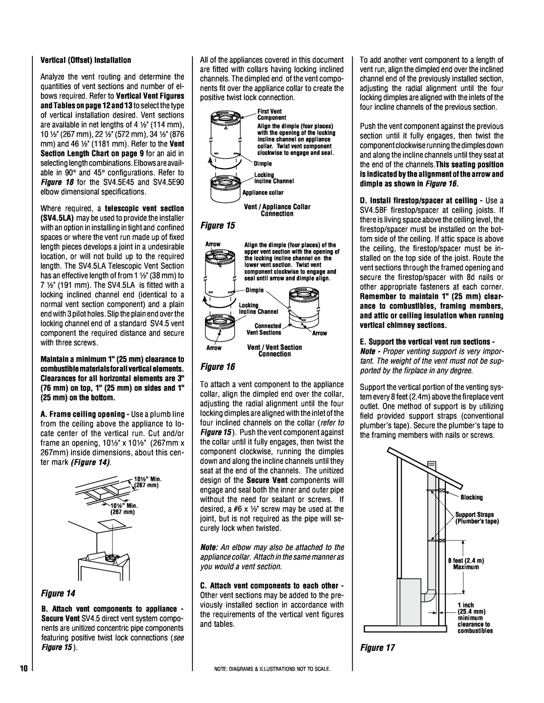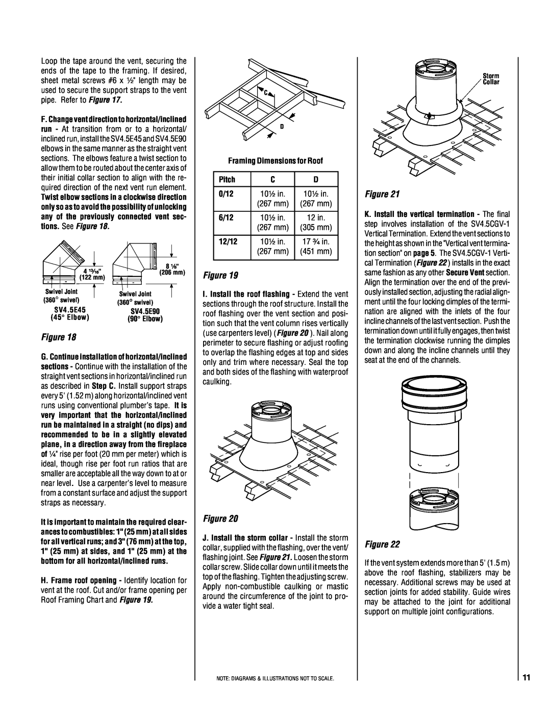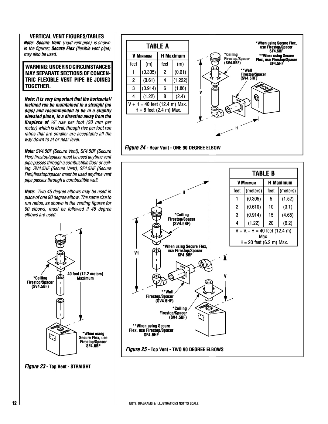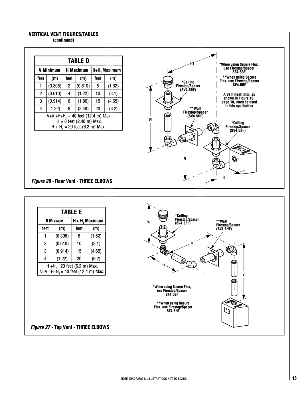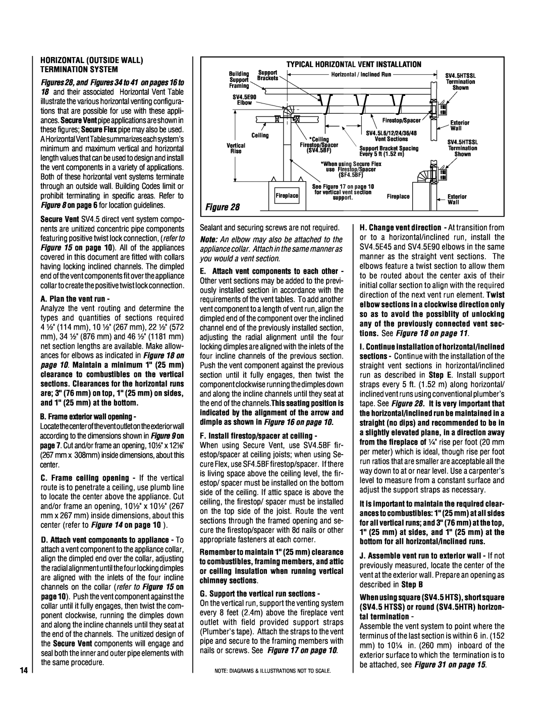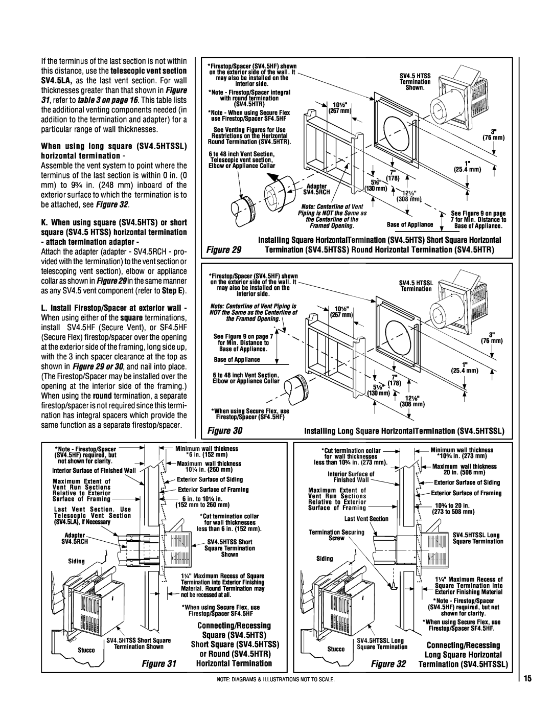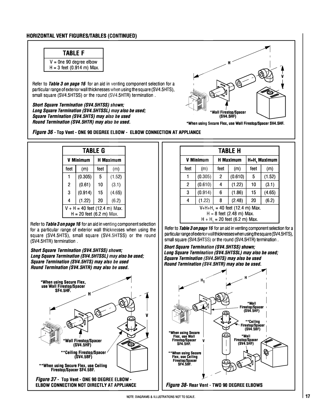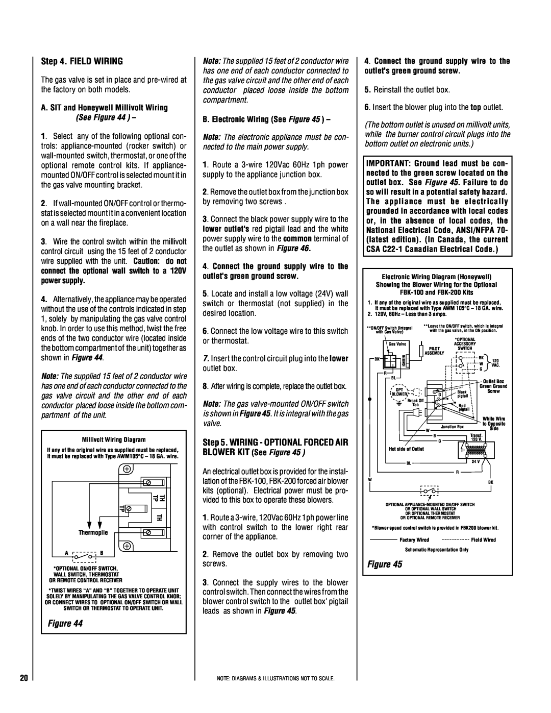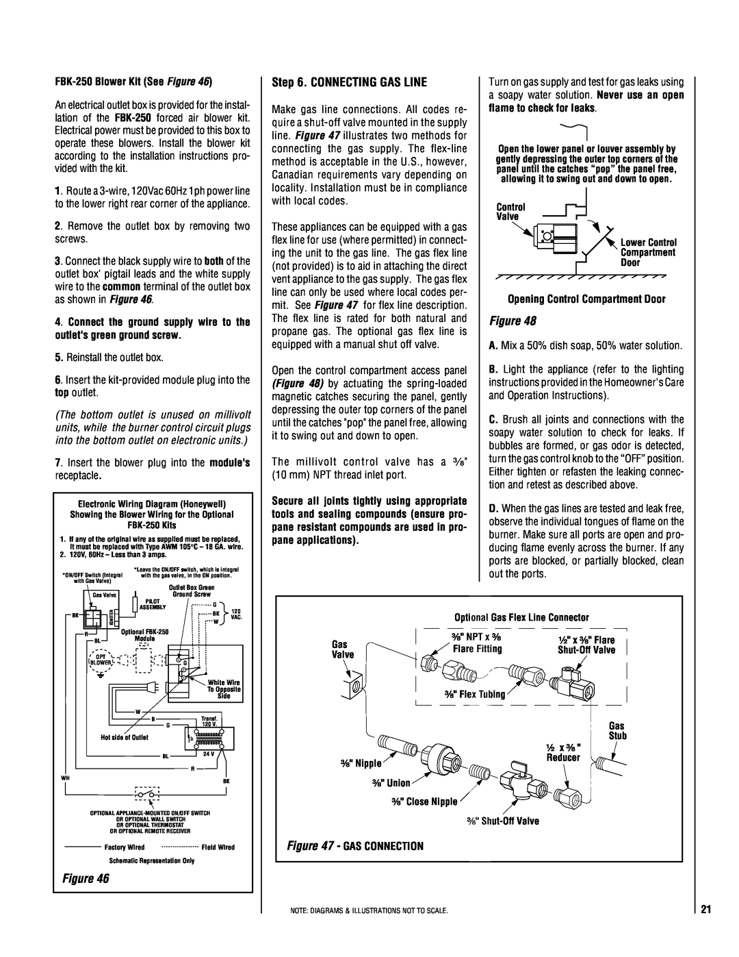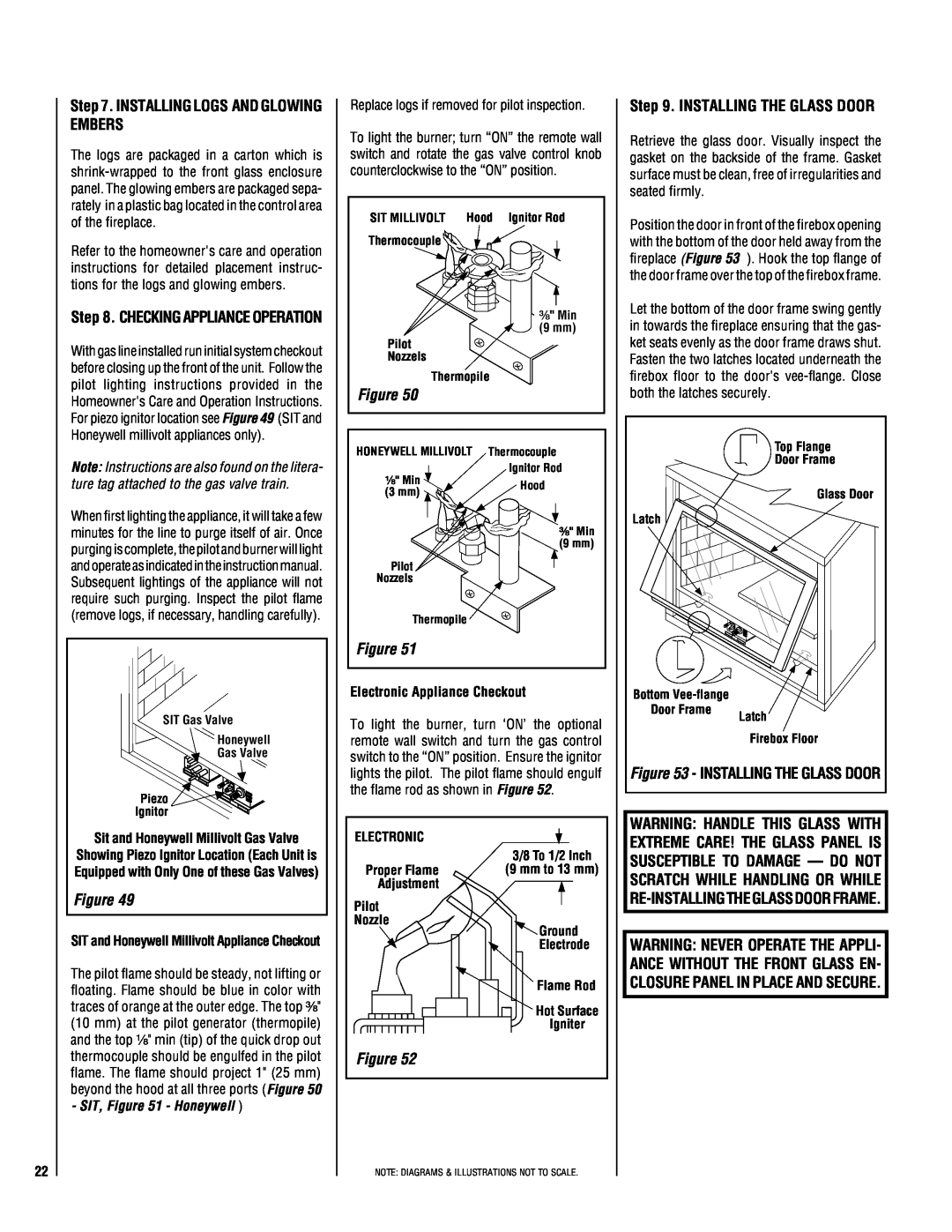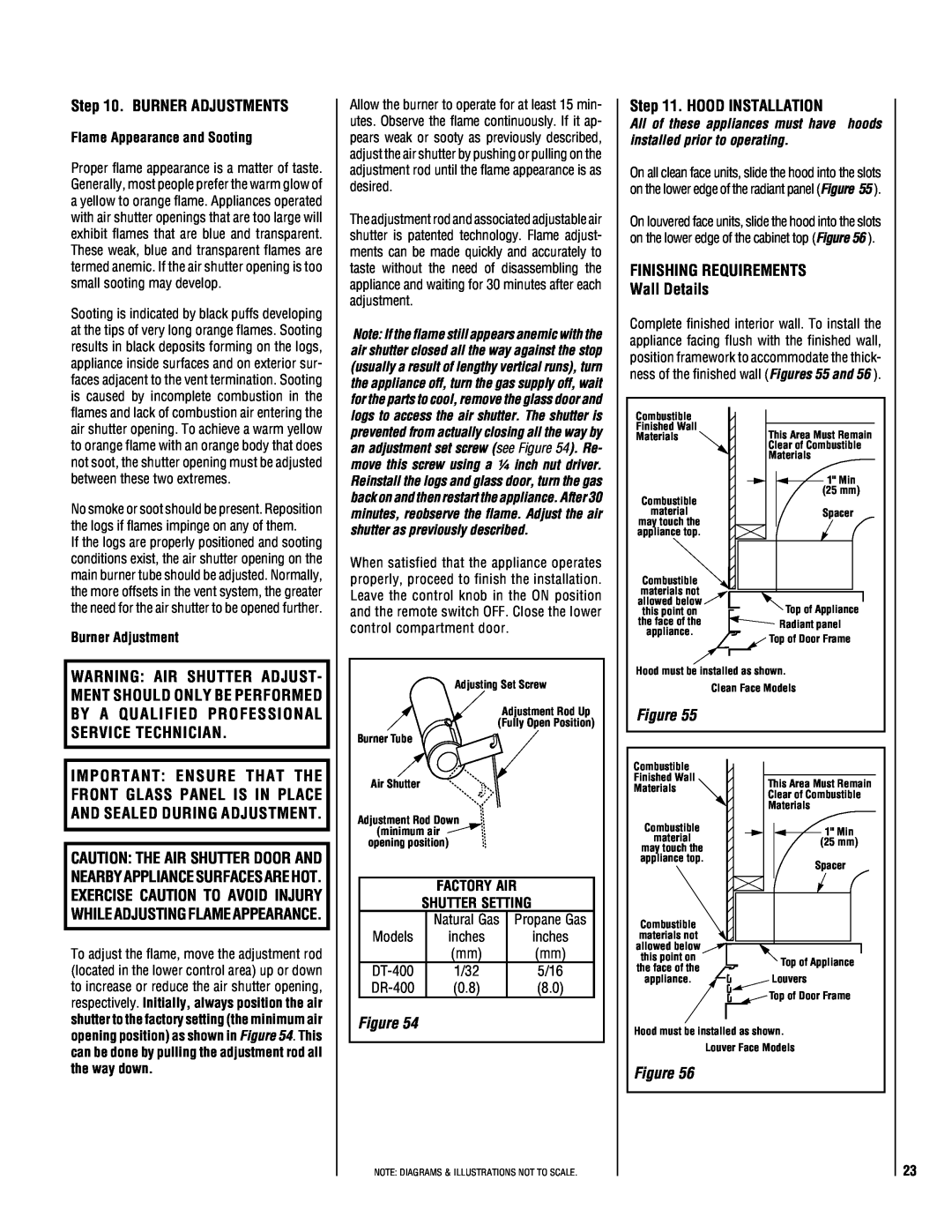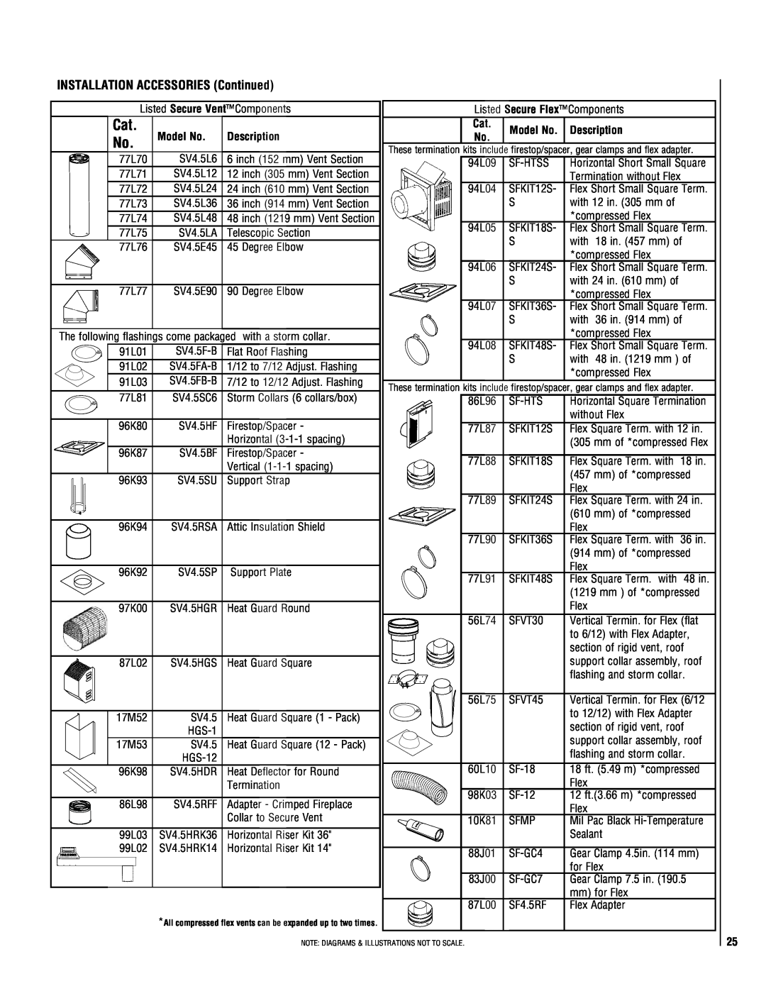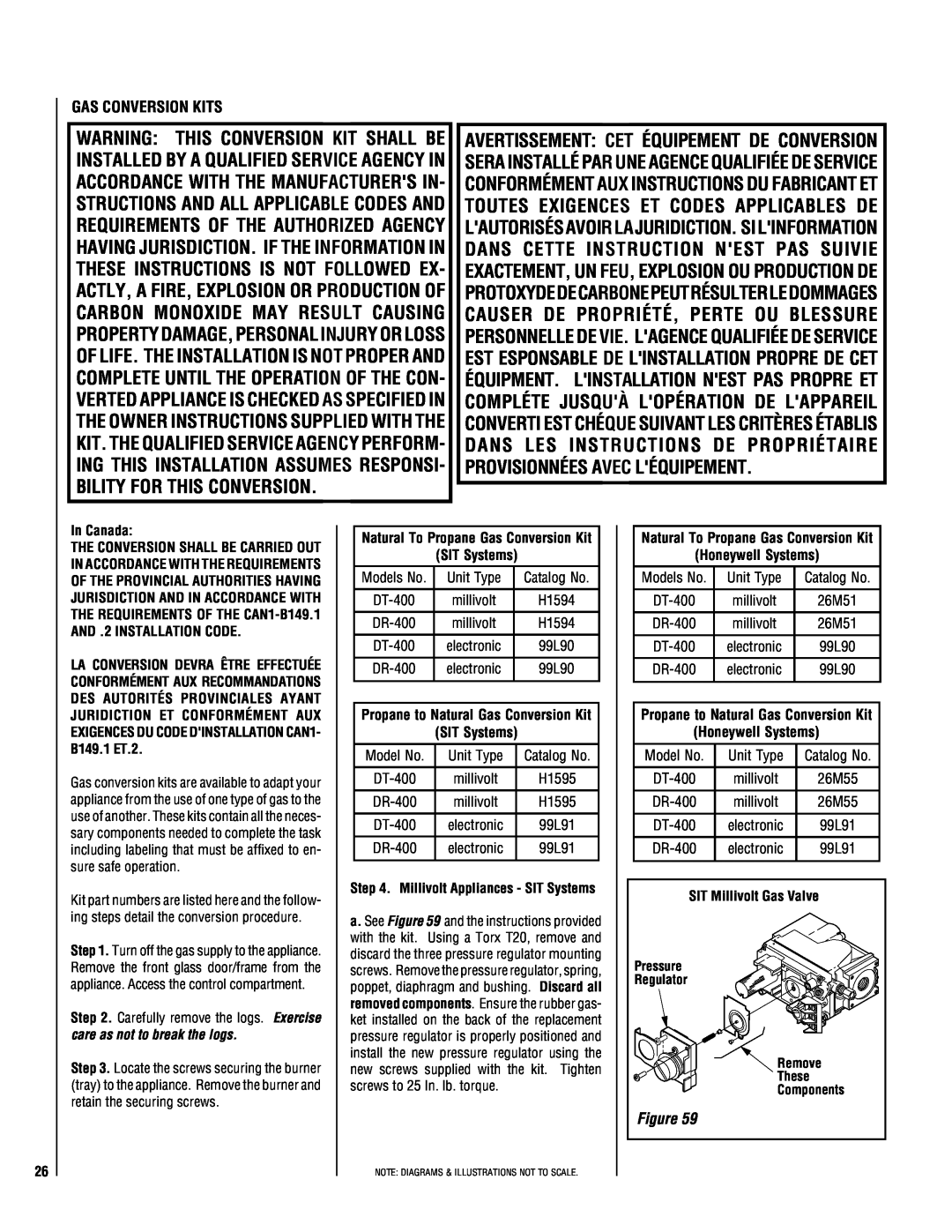
If the terminus of the last section is not within this distance, use the telescopic vent section SV4.5LA, as the last vent section. For wall thicknesses greater than that shown in Figure 31, refer to table 3 on page 16. This table lists the additional venting components needed (in addition to the termination and adapter) for a particular range of wall thicknesses.
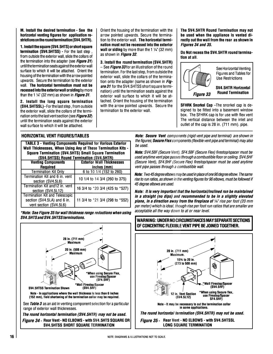
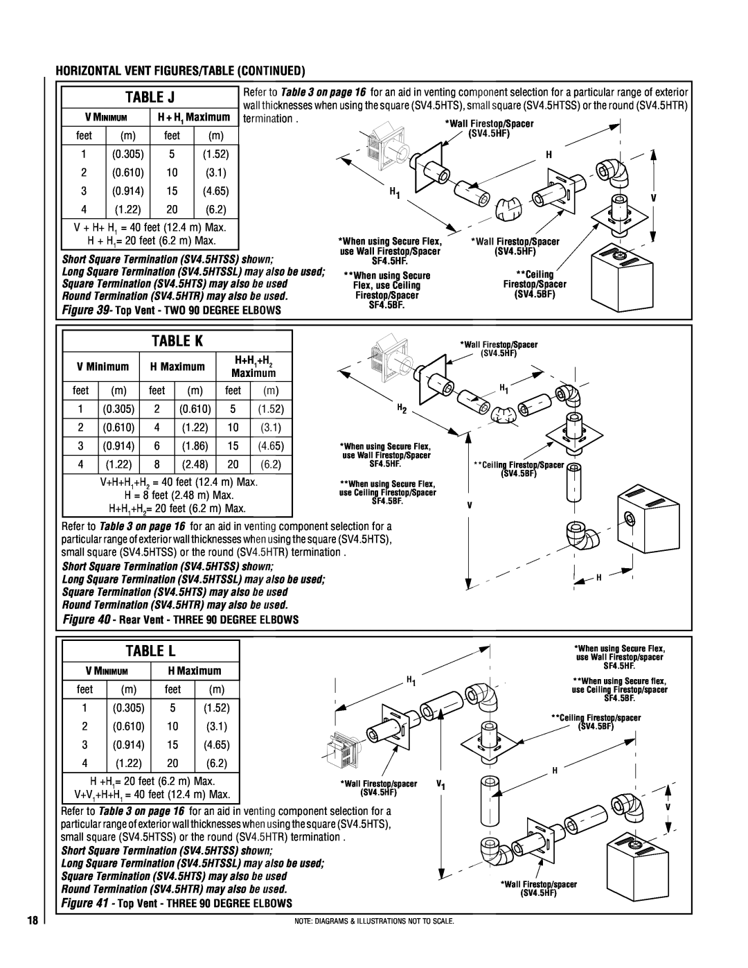
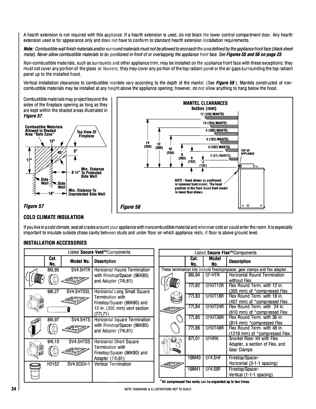
When using long square (SV4.5HTSSL) horizontal termination -
Assemble the vent system to point where the terminus of the last section is within 0 in. (0
mm)to 9³⁄₄ in. (248 mm) inboard of the exterior surface to which the termination is to be attached, see Figure 32.
K. When using square (SV4.5HTS) or short square (SV4.5 HTSS) horizontal termination
*Firestop/Spacer (SV4.5HF) shown on the exterior side of the wall. It may also be installed on the interior side.
*Note - Firestop/Spacer integral
with round termination
(SV4.5HTR)
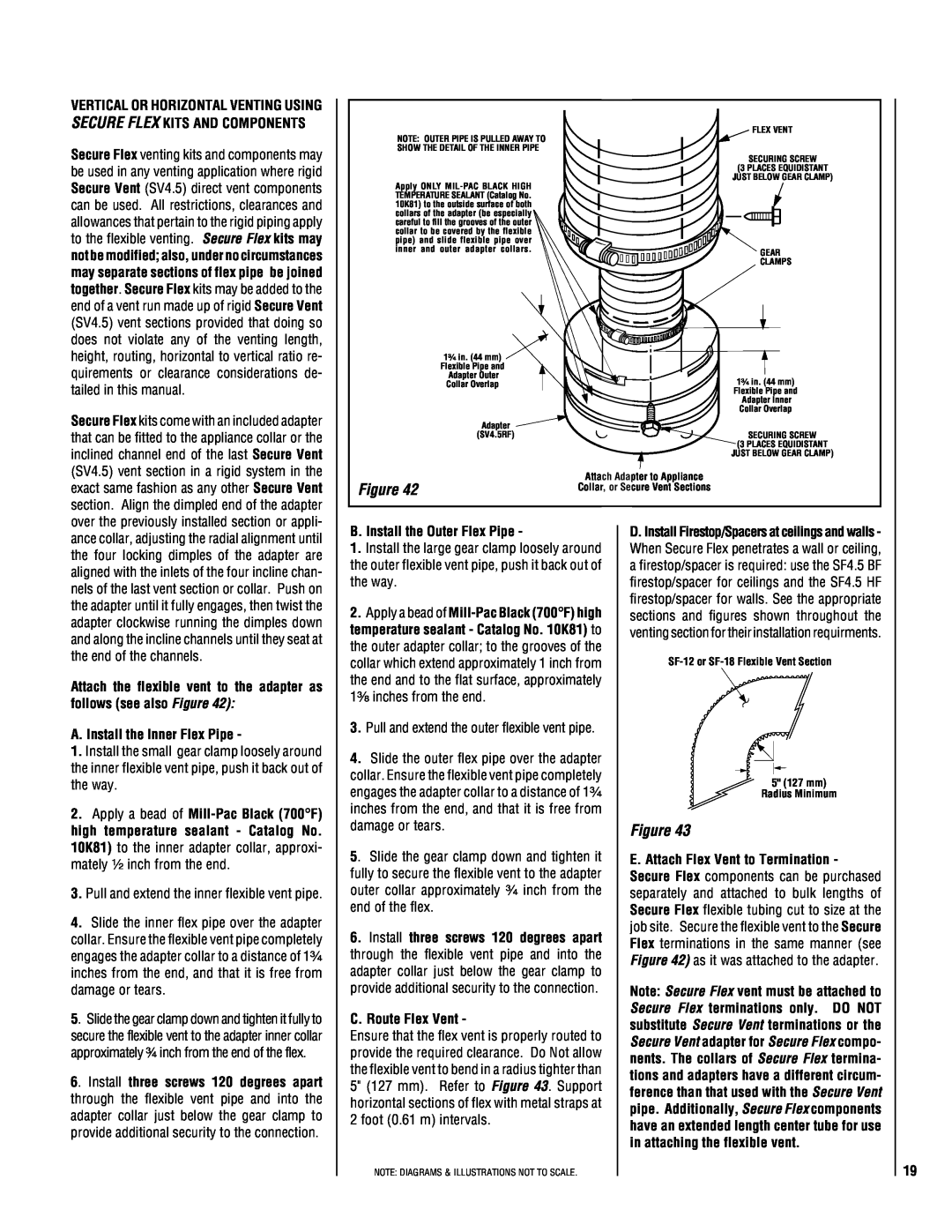
*Note - When using Secure Flex use Firestop/Spacer SF4.5HF
See Venting Figures for Use Restrictions on the Horizontal Round Termination (SV4.5HTR).
6 to 48 inch Vent Section, Telescopic vent section, Elbow or Appliance Collar
SV4.5 HTSS
Termination
Shown.
![]() 10¹⁄₂" (267 mm)
10¹⁄₂" (267 mm)
|
|
| 7" |
| |
|
|
| |||
Adapter | 5¹⁄₈" | (178) |
| ||
| |||||
|
|
| |||
SV4.5RCH | (130 mm) | ||||
|
|
| 12¹⁄₈" | ||
Note: Centerline of Vent |
|
|
| (308 mm) | |
|
| ||||
|
|
|
|
| |
|
|
|
|
| |
Piping is NOT the Same as |
|
|
| ||
the Centerline of the |
|
| Base of Appliance | ||
Framed Opening. |
|
| |||
3"
(76 mm)
1"
(25.4 mm)
See Figure 9 on page 7 for Min. Distance to Base of Appliance.
- attach termination adapter -
Attach the adapter (adapter - SV4.5RCH - pro- vided with the termination) to the vent section or telescoping vent section), elbow or appliance
Installing Square HorizontalTermination (SV4.5HTS) Short Square Horizontal
Figure 29 Termination (SV4.5HTSS) Round Horizontal Termination (SV4.5HTR)
collar as shown in Figure 29 in the same manner as any SV4.5 vent component (refer to Step E).
L. Install Firestop/Spacer at exterior wall - When using either of the square terminations, install SV4.5HF (Secure Vent), or SF4.5HF (Secure Flex) firestop/spacer over the opening at the exterior side of the framing, long side up, with the 3 inch spacer clearance at the top as shown in Figure 29 or 30, and nail into place. (The Firestop/Spacer may be installed over the opening at the interior side of the framing.) When using the round termination, a separate firestop/spacer is not required since this termi- nation has integral spacers which provide the same function as a separate firestop/spacer.
*Firestop/Spacer (SV4.5HF) shown on the exterior side of the wall. It may also be installed on the interior side.
Note: Centerline of Vent Piping is NOT the Same as the Centerline of the Framed Opening. ![]()
See Figure 9 on page 7
for Min. Distance to Base of Appliance.
Base of Appliance
6 to 48 inch Vent Section, Elbow or Appliance Collar
*When using Secure Flex, use
Firestop/Spacer (SF4.5HF)
Figure 30
SV4.5 HTSSL
Termination
![]() 10¹⁄₂" (267 mm)
10¹⁄₂" (267 mm)
3"
(76 mm)
1"
(25.4 mm)
7"
5¹⁄₈" (178)
(130 mm)
12¹⁄₈"
(308 mm)
Installing Long Square HorizontalTermination (SV4.5HTSSL)
*Note - Firestop/Spacer (SV4.5HF) required, but not shown for clarity.
Interior Surface of Finished Wall
Maximum Extent of
Vent Run Sections
Relative to Exterior
Surface of Framing
Last Vent Section. Use
Telescopic Vent Section
(SV4.5LA), If Necessary
Adapter
SV4.5RCH
Siding
![]() Minimum wall thickness *6 in. (152 mm)
Minimum wall thickness *6 in. (152 mm)
![]() Maximum wall thickness
Maximum wall thickness
10¹⁄₄ in. (260 mm)
![]() Exterior Surface of Siding
Exterior Surface of Siding
![]() Exterior Surface of Framing
Exterior Surface of Framing
6 in. to 10¹⁄₄ in.
(152 mm to 260 mm)
*Cut termination collar for wall thicknesses
less than 6 in. (152 mm).
SV4.5HTSS Short
Square Termination
Shown
*Cut termination collar
for wall thicknesses
less than 10³⁄₄ in. (273 mm).
Interior Surface of Finished Wall ![]()
Maximum Extent of
Vent Run Sections Relative to Exterior Surface of Framing ![]()
Last Vent Section
Termination Securing
Screw
Siding
![]() Minimum wall thickness *10³⁄₄ in. (273 mm)
Minimum wall thickness *10³⁄₄ in. (273 mm)
![]() Maximum wall thickness 20 in. (508 mm)
Maximum wall thickness 20 in. (508 mm)
![]() Exterior Surface of Siding
Exterior Surface of Siding
![]() Exterior Surface of Framing
Exterior Surface of Framing
![]() 10³⁄₄ to 20 in. (273 to 508 mm)
10³⁄₄ to 20 in. (273 to 508 mm)
SV4.5HTSSL Long
Square Termination
|
|
|
|
| 1¹⁄₄" Maximum Recess of Square |
|
|
|
|
| Termination into Exterior Finishing |
|
|
|
|
| Material. Round Termination may |
|
|
|
|
| not be recessed at all. |
|
|
|
|
| *When using Secure Flex, use |
|
|
|
|
| Firestop/Spacer SF4.5HF |
|
|
|
|
| Connecting/Recessing |
|
|
|
|
| Square (SV4.5HTS) |
| SV4.5HTSS Short Square | ||||
| Short Square (SV4.5HTSS) | ||||
Stucco | Termination Shown | ||||
|
|
|
| or Round (SV4.5HTR) | |
| Figure 31 | ||||
| Horizontal Termination | ||||
| SV4.5HTSSL Long |
Stucco | Square Termination |
|
Figure 32
1¹⁄₄" Maximum Recess of Square Termination into Exterior Finishing Material
*Note - Firestop/Spacer
(SV4.5HF) required, but not
shown for clarity.
*When using Secure Flex, use
Firestop/Spacer SF4.5HF.
Connecting/Recessing
Long Square Horizontal
Termination (SV4.5HTSSL)
NOTE: DIAGRAMS & ILLUSTRATIONS NOT TO SCALE.
15
