CHANGE LIGHT BULBS
![]() WARNING
WARNING
•Observe all safety warning and precautions! Improper light bulb removal or replacement could result in Death or Serious Injury.
•Disconnect power from opener before beginning this task.
•When replacing light cover, make sure wires are not pinched or near moving parts.
1.Disconnect power to door opener.
•Open powerhead light cover.
•Remove light bulb(s).
•Replace with maximum 100 Watt light bulb(s).
–Do NOT use light bulbs with greater than 100 Watt rating.
•Close powerhead light cover.
2.Reconnect power to door opener.
•Test light operation.
MOTION DETECTOR* - OVERVIEW
(Not available on all models)
Powerheads equipped with a motion detector sensor provide additional security when
exiting or entering the garage area.
*This sensor works by detecting body heat. Range of detection may be reduced when the temperature in the garage is close to body temperature.
NOTE: Detector positioning on the powerhead provides for monitoring below the powerhead.
OPERATION
•Detector sensor is always ON. There are NO user controls or adjustments.
•Lights automatically turn ON when a change is detected and will turn OFF after 4 minutes of no change.
•Motion detector sensor will not turn OFF lighting turned ON at the wall console.
•Lighting turned ON at the wall console will remain ON until wall console turns lighting OFF or opener
is used.
Motion Detector
RESET - OPEN/CLOSE TRAVEL LIMIT
Performing all ten (10) Limits/Force setting steps (pages
NOTE: The opener will not close the door automatically unless the
©2010 The Genie Company
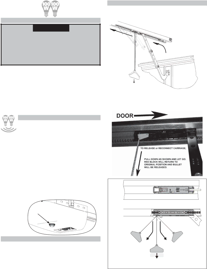
CARRIAGE ENGAGE/DISENGAGE
Use Release Handle to manually connect or release chain or belt bullet to Carriage.
TO RELEASE CARRIAGE:
1. Pull handle DOWN then let go.
2. Manually move door until carriage releases from bullet.
3. Raise or lower door manually.
| NOTICE |
|
| IFDOORBECOMESOBSTRUCTED |
|
Release | PULLDOWNONHANDLE | DOOR |
PULL |
| |
Handle |
|
TO RECONNECT CARRIAGE:
1.Verify RED block is in the UP position.
2.Manually move door until carriage engages bullet.
3.Raise or lower door using remote or wall console.
FIG. 6-3 Carriage Release
DOOR 
ENGAGE | DISENGAGE |
(for installation) | (for installation) |
TO REENGAGE PULL | TO DISENGAGE |
DOWN AND TOWARD | PULL DOWN AND |
POWERHEAD THEN | TOWARDS DOOR |
LET GO | THEN LET GO |
TO RELEASE or RECONNECT CARRIAGE, |
|
PULL DOWN AND LET GO |
|
FIG. | 19 |
12/2010 |