Zanussi ZCGHL55X manual Connecting to GAS, Connection to the Electricity Supply

Page 45

5. CONNECTING TO GAS

This appliance is designed to be installed with an


appliance flexible connection only. Supply piping should


not be less than R³/8 (³/8" B.S.P.). Connection is made


to the Rc½ (½" B.S.P.) female threaded entry pipe


located just below the hotplate level on the rear left hand


side of the appliance.


Carry out a gas tightness test after connecting to the


gas supply.


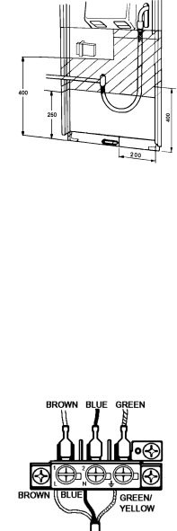
The gas bayonet connector must be fitted in the shaded


area indicated in Fig. 3. Take into account that it must


be possible to pull the appliance forward sufficiently.


The hose must not get caught on the stability bracket.

Fig.3


All dimensions in mm

IMPORTANT: FLEXIBLE TUBING USED MUST

COMPLY WITH BS. 669 CURRENT EDITION. L.P.G. FLEXIBLE CONNECTIONS MUST BE OF A TYPE SUITABLE FOR L.P.G. AND CAPABLE OF OPERATION UP TO 50MBAR AND TO CARRY A RED STRIPE, BAND OR LABEL.

NOTE: ONLY LIQUID SEALANTS CAN BE USED IN THREADED GAS CONNECTIONS. DO NOT USE P.T.F.E. TAPE.

6. CONNECTION TO THE ELECTRICITY SUPPLY

WARNING: THIS APPLIANCE MUST BE EARTHED. DO NOT EARTH THIS APPLIANCE TO THE GAS SUPPLY PIPING.

This appliance must be connected to 230V-240V A.C. 50 Hz supply. It is supplied with 2 metres of 5 amp 3 core cable incorporating a moulded 13 amp rated plug, fitted with a 3 amp fuse, which can be plugged directly into the nearest suitable socket. Ensure the plug is accessible to the user. If this is not long enough, the supply cable can either be:-

(i)Replaced totally by a longer cable at least 0.75mm2 nominal cross sectional area (24/0.2mm).

(ii)Extended by using a B.E.A.B. approved 3-way sealed flex connector with integral flex clamps.

IF THE MOULDED PLUG IS CUT FROM THE CABLE FOR ANY REASON, IT MUST BE DESTROYED OR DISPOSED

OF SAFELY, AS THE PROTRUDING


WIRES WILL BE AN ELECTRIC SHOCK

Fig.4

HAZARD.

If any other type of plug is used it should incorporate a


3 amp fuse in either the plug or at the distribution


board. If the cable has to be threaded through small


apertures in cabinets etc., it may be disconnected from


the appliance, then re-connected as shown in Fig.4.


DO NOT EXTEND THE CABLE USING PLASTIC OR

CERAMIC CONNECTION TERMINAL BLOCKS AND/OR INSULATION TAPE.

ALL EXTERNAL WIRING BETWEEN THE APPLIANCE AND THE ELECTRICAL SUPPLY SHALL COMPLY WITH I.E.E. WIRING REGULATIONS.

If the wiring is extended or a completely new cable fitted a 3-pin 13A plug should be fitted. (See Fig.4).

45

Image 45
Contents ZCGHL55X Introduction For your safetyContents Hotplate and Grill Lighting the applianceMain oven Top ovenTo turn off any burner Grill Prior to using the grillHeat control Grill panCooking positions PreheatingPutting food on the grid Burner sizes HotplateFor your safety Need. Do not overfill pans Helpful hintsOvens Heat zonesOven shelves Shelf positions are counted from the top downwards Baking trays and dishesCondensation RoastingPut the dishes in the centre of the shelf Oven cooking chart Main ovenMins. per ½kg 1 lb and 25 mins Fruit pie shortcrust 25 35 mins Oven cooking chart Top oven Duck and duckling Shelf on Mins. per ½kg 1 lb Baked custard 50 60 mins Electronic Minute Minder To USE the Minute Minder To Cancel the Minute Minder Lock Feature Main Oven only Food preparation slow cooking Slow cookingGeneral points for slow cooking Frozen foods Hotplate Care and cleaning For your safetyGrill When replacing hotplate burner partsFollow the oven cleaning cycle regularly General Oven cleaning cycleTo remove the outer glass Cleaning between the outer and inner glass doorsLocation Installing the appliance For your safetyPositioning Appliance dimensionsGeneral information For your safety Connecting to the electricity supplyMoving your appliance Replacing the oven light bulb LCheck What is wrong and why?G H L 5 5 Problem 7 0 5 9 2 9 9 2 Service and spare partsCustomer Care Department Installation Instructions Dimensions Technical DataImportant Safety Requirements GAS Category Countries of DestinationProvision for Ventilation Grill Assembly Location of ApplianceParts Required Fitting the Stability Bracket Levelling the ApplianceConnection to the Electricity Supply Connecting to GASFIT a 3 AMP Fuse to the Plug Holder Pressure TestingChecking the Hotplate Checking the GrillChecking the Main Oven Checking the TOP OvenStandard guarantee conditions Guarantee ConditionsT E S G H L 5 5 X T E S Part Number311721700