5
CONFIGURING THE TR-IN-FE MODULE
This chapter describes how to configure the
■
■Setting Up a Module
■Setting Up a VLAN
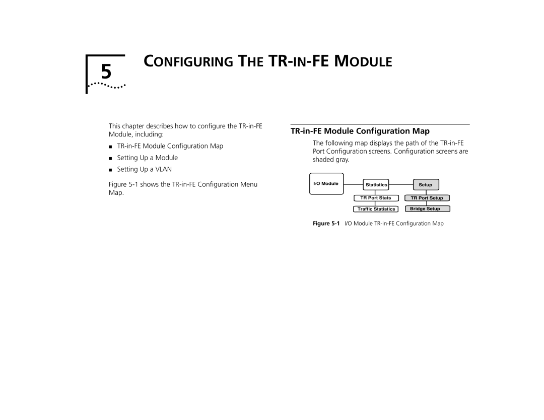
Figure 5-1 shows the TR-in-FE Configuration Menu Map.
TR-in-FE Module Configuration Map
The following map displays the path of the
I/O Module | Statistics | Setup |
| TR Port Stats | TR Port Setup |
| Traffic Statistics | Bridge Setup |