Setting Up a VLAN
This section describes how to extend VLANs into the
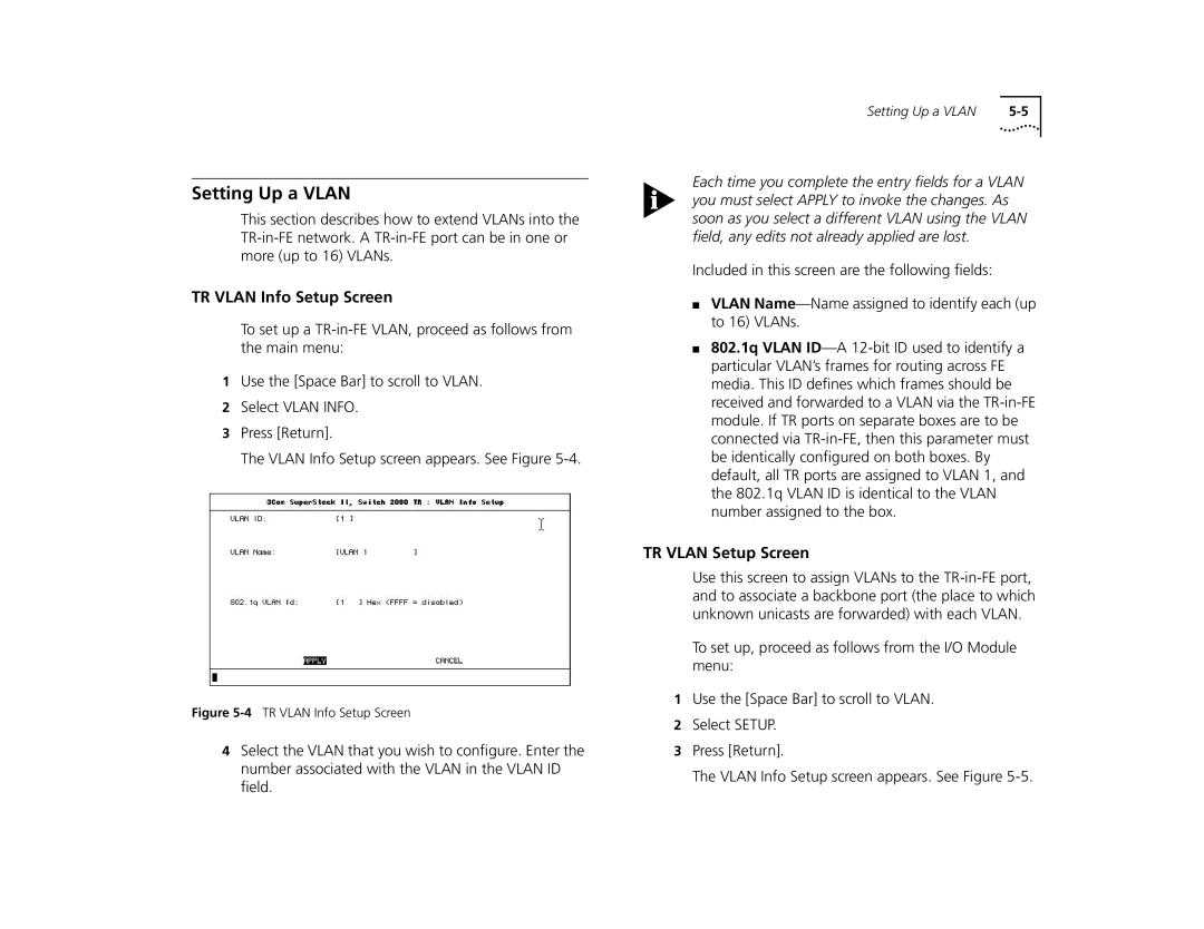
TR VLAN Info Setup Screen
To set up a
1Use the [Space Bar] to scroll to VLAN.
2Select VLAN INFO.
3Press [Return].
The VLAN Info Setup screen appears. See Figure
Figure 5-4 TR VLAN Info Setup Screen
4Select the VLAN that you wish to configure. Enter the number associated with the VLAN in the VLAN ID field.
Setting Up a VLAN |
Each time you complete the entry fields for a VLAN you must select APPLY to invoke the changes. As soon as you select a different VLAN using the VLAN field, any edits not already applied are lost.
Included in this screen are the following fields:
■VLAN
■802.1q VLAN
TR VLAN Setup Screen
Use this screen to assign VLANs to the
To set up, proceed as follows from the I/O Module menu:
1Use the [Space Bar] to scroll to VLAN.
2Select SETUP.
3Press [Return].
The VLAN Info Setup screen appears. See Figure